
User Manual
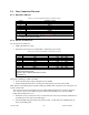
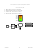
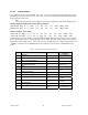

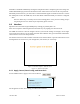
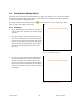
Table Of Contents
- 1.
- 1. Product Overview
- 2. Installation
- 3. Physical Description
- 4. Operation & Configuration
- 4.1 Browser-Based Setup and Status
- 4.2 LAN Setup
- 4.3 Login Screen
- 4.4 Interface
- 4.5 Setup Wizard (Bridge Mode)
- 4.6 Default IP Settings
- 4.7 IP Network Settings
- 4.8 Advanced IP Settings
- 5. Optimization & Troubleshooting
- 6. Specifications

120 40520-100a ViPR User Manual
21
3.1 User Connector Pin-outs
3.1.1 Ethernet LAN Port
Table 4 - Pin-out for IEEE-802.3af RJ-45 receptacle contacts
Contact 10/100Base-T signal
1 TXP
(1)
2 TXN
(1)
3 RXP
(1)
4 SPARE +
5 SPARE +
6 RXN
(1)
7 SPARE -
8 SPARE -
SHELL Shield
(1) The name shows the default function. Given the auto-MDIX capability of the Ethernet transceiver,
TX and RX function could be swapped.
3.1.2 SETUP & COM Ports
For serial ports considerations:
• ViPR radiomodem is a DCE
• Equipment connected to the ViPR SETUP / COM serial port is a DTE
Table 5 - Pin-out for DCE J11A & B, 9-contact DE-9 connector
Contact EIA-232F Function Signal Direction
1 DCD DTE
Í
DCE
2 RXD DTE
Í
DCE
3 TXD DTE
Î
DCE
4
(1)
DTR DTE
Î
DCE
5 GND DTE --- DCE
6
(2)
DSR DTE
Í
DCE
7
(3)
RTS DTE
Î
DCE
8 CTS DTE
Í
DCE
9 RING
(4)
DTE --- DCE
(1) Depends on connection control mode
(2) Always keeps DSR asserted
(3) Ignores status of RTS (internally always asserted)
(4) For future use
DCD (pin 1) handling by ViPR unit UART
• Asserts the DCD signal while sending data on the UART
• Negates the DCD signal when it no longer has data queued up for TX on the UART
DTR (Data Terminal Ready) (pin 4) signal handling by ViPR UART - Depends on the serial port's con-
nection control mode.
The connection control mode dictates how the ViPR establishes/breaks the connection (referred
to as "session") between the ViPR serial ports and the selected ViPR service (CLI, Serial/RF
bridge, Online Diagnostics, etc.)
• Permanent (3-wire) connection control - In this mode, the session is permanently established, so
the ViPR ignores the status of the DTR signal.
• Switched (DTR bringup/teardown) connection control - In this mode, the ViPR monitors the
status of the DTR signal.