
User Manual
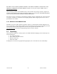
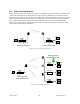
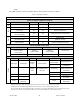
Table Of Contents
- 1.
- 1. Product Overview
- 2. Installation
- 3. Physical Description
- 4. Operation & Configuration
- 4.1 Browser-Based Setup and Status
- 4.2 LAN Setup
- 4.3 Login Screen
- 4.4 Interface
- 4.5 Setup Wizard (Bridge Mode)
- 4.6 Default IP Settings
- 4.7 IP Network Settings
- 4.8 Advanced IP Settings
- 5. Optimization & Troubleshooting
- 6. Specifications
120 40520-100a ViPR User Manual
19
3. Physical Description
Figure 7 - ViPR Front Panel
The front panel only has connections and indicators. They are:
• One standard RJ-45 auto-sensing 10/100 UTP Ethernet connection with Auto-MDIX. Supports
direct connection to both Terminal Devices and Ethernet hubs or switches without resorting to
crossover cables. LED indicators make it simple to verify that Ethernet cables and connections
are good.
• Two DE-9F RS232 ports. Serial baud rates from 300 to 115,200 are supported. ViPR units are
factory set (default) for 115,200 b/s, 8 bits, no parity, and 1 stop bit.
• The antenna connector for the transceiver is a female 50-ohm TNC type.
• One right-angle power connector. The 10 to 30 VDC wide-range switching power supply permits
powering from 12 volt as well as 24 volt systems, and the high-efficiency switching design runs
cooler with less loss.