
User Manual
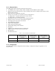
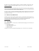
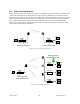
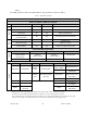
Table Of Contents
- 1.
- 1. Product Overview
- 2. Installation
- 3. Physical Description
- 4. Operation & Configuration
- 4.1 Browser-Based Setup and Status
- 4.2 LAN Setup
- 4.3 Login Screen
- 4.4 Interface
- 4.5 Setup Wizard (Bridge Mode)
- 4.6 Default IP Settings
- 4.7 IP Network Settings
- 4.8 Advanced IP Settings
- 5. Optimization & Troubleshooting
- 6. Specifications
120 40520-100a ViPR User Manual
16
Figure 2 – Antenna
2.2.3 RF Path and communications range
The range of the ViPR radiomodem is dependent on terrain, RF (radio frequency) path obstacles, and an-
tenna system. To assure reliable communications, a competent professional should study the RF path to
determine what antennas are required and whether or not a repeater is needed.
2.2.4 Antennas
The antennas listed in Table 1, page 13 were tested and typed for maximum gain. These antennas are
FCC-approved for use with the ViPR product. Similar antenna types from other manufacturers are also
acceptable.
2.3 Network application
The ViPR radiomodem is suited to a variety of point-to-point or point-to-multipoint applications. This
section gives an overview of some common configurations.
2.3.1 Modes
2.3.1.1 Bridge mode
Bridge mode provides for fast set-up. IP bridging allows for quick deployment of basic point-to-point and
point-to-multipoint networks with minimal configuration to all units on a same network. Bridge mode
carries ARP and is transparent to any IP-based or IP-encapsulated protocols.
2.3.1.2 Router mode
Used in advanced networks, router mode enables OIP optimization for reduced overhead and improved
throughput, and supports more complex network topologies such as store-and-forward links. Only one
radio model is needed because any ViPR unit can be configured for bridge or router mode, router gateway
(access point), remote station, or even as a combined store-and-forward remote with a local drop.
2.3.2 Connections
The connections required are shown in Figure 3 below and in Figure 4 on the next page. While serial
and/or Ethernet RTU or PLC are shown in the diagrams, master stations often use a PC running an appli-
cation designed to communicate with remote RTUs or PLCs, or intelligent controllers.