ViPR Wireless Radio Modem User Manual Preliminary – For Internal Use Only Copyright DATARADIO Inc. April 2007 Part no.
Table of Contents 1. PRODUCT OVERVIEW ...............................................................................................................................11 1.1 INTENDED AUDIENCE .................................................................................................................................... 11 1.2 GENERAL DESCRIPTION................................................................................................................................. 11 1.2.1 Characteristics........
4.8.1 4.8.2 Unit Status ...........................................................................................................................................35 Setup (Basic)........................................................................................................................................36 4.8.2.1 4.8.2.2 4.8.2.3 4.8.2.4 4.8.2.5 4.8.3 Setup (General) ................................................................................................................................
FIGURE 10 - ENTER NETWORK PASSWORD SCREEN (APPEARANCE MAY VARY WITH BROWSER USED) ....................... 26 FIGURE 11 - WEB USER INTERFACE – WELCOME SCREEN ......................................................................................... 27 FIGURE 13 – ATTENTION SUB-WINDOW...................................................................................................................... 27 FIGURE 14 - SETUP WIZARD - PAGE ONE ........................................................................
TABLE 7 – DECODING SAMPLE OUTPUT FOR ROUTER MODE ..................................................................................... 25 APPENDIX 1 - DATA TELEMETRY WARRANTY ...........................................................................................................
What's New in this version History Version 1.00, Preliminary, 12December 2006 • Draft leading to Initial release of Dataradio® ViPR™ wireless radio modem User Manual Version 2.00, Preliminary, 11 April 2007 • Changed iPR radio name to ViPR. Made numerous updates to specifications. Removed references to HiPR-900.
About Dataradio Dataradio is a leading designer and manufacturer of advanced wireless data products and systems for mission critical applications. Our products are found at the heart of mobile data and SCADA networks around the world. With over 25 years dedicated to data technology and innovation, Dataradio is the premier source for wireless data solutions.
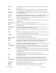
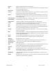
Definitions Item Definition Access Point Communication hub for users to connect to a LAN. Access Points are important for providing heightened wireless security and for extending the physical range of service a wireless user has access to. AES Advanced Encryption Standard (AES) Airlink Physical radio frequency connections used for communications between units. ARP Address Resolution Protocol – Maps Internet address to physical address.
Gateway HDX HiPR-900 ViPR™ HTTP IPCONFIG LNK/ACT LED MAC Midspan PSE MTU NAT Network Network speed Node OIP OTA Parallel Decode PHY Ping PLC Powered Device PWR LED RIPv2 Router 120 40520-100a A device that interconnects networks with different, incompatible communications protocols. Half Duplex. Data transmission that can occur in two directions over a single line, using separate Tx and Rx frequencies, but only one direction at a time.
RS-232 RTU Industry–standard interface for data transfer. Remote Terminal Unit. A user-provided SCADA device used to gather information or control other devices. Rx/Tx LED Transmission /Reception activity SCADA Supervisory Control And Data Acquisition. A general term referring to systems that gather data and/or perform control operations. SNTP Simple Network Time Protocol - Protocol for synchronizing the clocks of computer systems over packet-switched, variable-latency data networks.
1. Product Overview This document provides information required for the operation and verification of the DATARADIO® ViPR narrowband Ethernet IP radiomodem. 1.1 Intended Audience This manual is intended for system designers, professional installers, and maintenance technicians. 1.2 General Description Dataradio’s ViPR radiomodem is a DSP-based narrowband Ethernet IP radio that operates in the UHF (406.1-512 MHz) and VHF (136-174 MHZ) frequency ranges.
1.2.1 Characteristics The ViPR product has the following operational characteristics: • An ViPR RF deck, frequency range of 406.1-470 MHz, 450-512 MHz and 136-174 MHz • High-speed user-selectable data rates of up to 32 Kbps in full channel, 16 Kbps in half channel, and 8 Kbps in quarter channel. • Built-in transceiver adjustable to 10 watts.
1.2.3 Accessories and Options Table 2 lists various accessory items available for the ViPR Wireless Modem. Table 2 - Accessories Accessory Dataradio Part Number ViPR DIN-rail Mounting Kit 250-5099-005 (150-5099-005) 7 dB 450-470 MHz Yagi Antenna Kit 250-0241-507 10 dB 450-470 MHz Yagi Antenna Kit 250-0241-510 Antenna kits For information on accessories and options, contact your sales representative. In the United States, call 1-800-992-7774 or 1-507833-8819.
BE SURE TO HAVE THE EQUIPMENT MODEL AND SERIAL NUMBER, AND BILLING AND SHIPPING ADDRESSES ON HAND WHEN CALLING. You may also request an RMA online at www.dataradio.com/rma. When returning a product, mark the RMA clearly on the outside of the package. Include a complete description of the problem and the name and telephone number of a contact person. RETURN REQUESTS WILL NOT BE PROCESSED WITHOUT THIS INFORMATION. For units in warranty, customers are responsible for shipping charges to Dataradio.
2. Installation 2.1 UL Approved for Class I, Division 2 or Zone 2 The ViPR radiomodem is suitable for use in Class I, Division 2, Groups A, B, A, D or non-hazardous locations. To meet UL compliance, the ViPR unit must be installed in an enclosure and power must be supplied by a SELV (Safety Extra Low Voltage), non-energy hazardous source. This device is powered by a terminal block (+). Warning – Explosion Hazard – Do not disconnect while circuit is live unless area is know to be nonhazardous.
Figure 2 – Antenna 2.2.3 RF Path and communications range The range of the ViPR radiomodem is dependent on terrain, RF (radio frequency) path obstacles, and antenna system. To assure reliable communications, a competent professional should study the RF path to determine what antennas are required and whether or not a repeater is needed. 2.2.4 Antennas The antennas listed in Table 1, page 13 were tested and typed for maximum gain. These antennas are FCC-approved for use with the ViPR product.
Figure 4 shows a common connection scenario. The TX/RX antenna is required for basic operation. The power connection allows for a wide range of input DC power, whether the user system is a nominal 12 or 24 VDC supply system. A setup PC can be connected via the serial port, allowing for setup and configuration of the ViPR unit as well as local and remote diagnostics. It may be left connected at all times but is not required for normal operation once the unit has been configured.
2.5 Point to Point System Shown below are typical “point to point” and “point to multipoint” connections between ViPR units. The connections indicated allow for either Ethernet or serial interfaces. The Ethernet connection provides Ethernet IP connectivity for network devices. In bridge mode, all the network devices are on the same IP Subnet. In router mode, the Ethernet connection on Master unit and the remote(s) use different IP Subnets.
3. Physical Description Figure 7 - ViPR Front Panel The front panel only has connections and indicators. They are: • One standard RJ-45 auto-sensing 10/100 UTP Ethernet connection with Auto-MDIX. Supports direct connection to both Terminal Devices and Ethernet hubs or switches without resorting to crossover cables. LED indicators make it simple to verify that Ethernet cables and connections are good. • Two DE-9F RS232 ports. Serial baud rates from 300 to 115,200 are supported.
LEDS The ViPR unit has five dual-color LED indicators. Their functions are shown in Table 3.
3.1 User Connector Pin-outs 3.1.1 Ethernet LAN Port Table 4 - Pin-out for IEEE-802.3af RJ-45 receptacle contacts Contact 10/100Base-T signal (1) 1 TXP (1) 2 TXN (1) 3 RXP 4 SPARE + 5 SPARE + (1) 6 RXN 7 SPARE 8 SPARE SHELL Shield (1) The name shows the default function. Given the auto-MDIX capability of the Ethernet transceiver, TX and RX function could be swapped. 3.1.
- Upon DTR assertion: the session in established (bringup) phase Upon DTR negation: the session in closed (teardown) phase CTS (Clear to Send) (pin 8) signal handling by the ViPR UART • If CTS-based flow control is not used, always asserts CTS • If CTS-based flow control is used: ♦ Asserted – If level of unprocessed data in internal RX buffers is below a threshold mark water- ♦ Negated – If level of unprocessed data in internal RX buffers is above a threshold mark water- 120 40520-100a 22 ViPR Us
3.2 Diagnostic Connections The ViPR units continually monitor and report on their environmental and operating conditions. The diagnostic information is in TCP format and is available via any telnet session to port 6272. Transmission of online diagnostics may be enabled or disabled at any station or stations without affecting their ability to communicate with other stations. Diagnostics can be sent anywhere, including being back hauled.
Table 6 - Simplified rating of output value representing Packet Error Rate (PER) Figure 8 - Packets Counts for PER ♦ Signal RSSI: Decimal level in calibrated dBm ♦ Background RSSI: Decimal level in calibrated dBm ♦ Forward power: Decimal indications in milliwatts ♦ Reverse power: Decimal indications in milliwatts Value –10 Bad Value –20 Mediocre Value –30 Good Value –40 Very Good Value –50 Excellent “Bad” Packets Counts for Packet Error Rate Incoming Packets 120 40520-100a Basic Packet Header
3.2.2.1 Output Samples From command window, type telnet nnn.nnn.nnn.nnn 6272 and the unit’s diagnostic output will display on screen (where nnn.nnn.nnn.nnn is your unit’s address in dot decimal format) (Thinning value must not be zero). Note: No overhead is generated in the ViPR unit if no online diagnostic connection is actually made.
4. Operation & Configuration 4.1 Browser-Based Setup and Status A built-in web server makes configuration and status monitoring possible from any browser-equipped computer, either locally or remotely. Status, configuration, and online help are available without requiring special client software. Setup is password-protected to avoid tampering or unauthorized changes.
Dataradio recommends immediately running the Setup Wizard. Once completed, proceed to change the ViPR radiomodem login password as detailed in section 4.8.4.1 below. Do not lose the new password! Should the password be lost, you will need to contact Dataradio support as detailed in section 1.3 earlier. For subsequent access to the ViPR unit, use the User Name and Password that you will have configured. Note: The User Name entry is currently not an access-limiting factor.
After making an entry into a dialog box, click on Apply to temporarily apply the value(s) entered to the relevant parameter(s). If not satisfied, click on Cancel button to restore to the value(s) present before a change was made. Note: Cancel command only affects the dialog boxes or radio buttons in the opened window. If needed, go to other Submenu(s) and make more entries. Click Apply before leaving each window. When finished, click the Save Config button to make all changed entries permanent.
4.5 Setup Wizard (Bridge Mode) Four pages of the quick setup wizard have buttons to “Apply your changes” or to “Cancel your changes” during the setup process. Once all five pages are done, use the “Save Config” and the “Reset Unit” buttons to make parameter settings permanent. If a change is made to any parameter marked: Unit” in order for the change to take effect. you will need to do a “Save Config” and a “Reset 4.5.1 Procedure 1.
4. On page three (Figure 15) of the Setup Wizard, read the on-screen instructions. Once the Encryption Pass Phrase is entered, note the Encryption Key. Click Apply Your Changes. Wait for the Progress bar activity to stop (right side of the Status bar). Click on Proceed to Next Step. If no change is made to the Encryption dialog box, click on Proceed to Next Step. Important: Be sure to record your encryption pass phrase for future reference. Figure 15 - Setup Wizard - Page Three 5.
6. On page five (Figure 17) of the Setup Wizard, read the onscreen instructions. If configuring for Router mode, you have completed. For Bridge mode, click the “Switch to Bridge mode” button and follow the instructions below for both modes of operation: Click one of the “Save Config” buttons. Wait for the Progress bar activity to stop The status reports: “Success. Click on “Reset Unit” button. Wait for the Progress bar activity to stop.
4.6 Default IP Settings • Default RF mode is Remote • Default IP Forwarding mode is Bridge • Time Division Duplex (TDD) RF protocol is enabled by default 4.6.1 Ethernet Interface • MAC: 00:0A:99:XX:YY:ZZ • IP ADDR: 192.168.204.1 • NETMASK: 255.255.255.0 • Default Gateway: 0.0.0.0 • DHCP Server Enabled 4.6.2 RF Interface • MAC: 00:XX:YY:ZZ • IP ADDR: 10.XX.YY.ZZ • NETMASK: 255.0.0.0 • TCP Proxy Disabled Notes: RF Interface IP settings are irrelevant in bridge mode.
4.7.2 IP Network Settings in Bridge Mode Referring to Figure 20, set one of the ViPR unit as a Master. Set the IP addresses and IP netmask. In the illustration, Host, RTU, ViPR Master, and Remote are part of the same IP subnet. This setup not only acts as a transparent Bridge but also provides IP Services (web pages, Terminal Server, FTP etc…). ViPR Master ViPR Remote DHCP Server DHCP Server RF IP: 10.x.y.z MASK: 255.0.0.0 Eth1 IP: 172.30.1.3 MASK: 255.255.255.0 RF IP: 10.a.b.c MASK: 255.0.0.
4.7.4 IP Network Settings in Router Mode (with Router) Referring to Figure 22, set one of the ViPR unit as a Master. Set the Router mode on the Master and Remote. Set the Eth1 IP addresses and IP netmask of both Master and Remote. Keep the RF IP setting as is if not using the 10.0.0.0 IP network on your Intranet. Enable the Dynamic Registration on both Master and Remote. Add Default Gateway to the RTU Enable RIPv2 on Master In the illustration, Host and RTU are part of different IP subnet.
4.8 Advanced IP Settings 4.8.1 Unit Status Figure 23 - Unit Status Item Banner Station Name System ID Local Time Operating mode IP Forwarding mode Sync Status Description Displays ViPR unit software revision information retrieved from the connected unit. Have this information handy if contacting Dataradio support. Displays name of connected unit.
Factory-set. Shows the territory the unit has been configured for operation and approved by the appropriate governmental authority. Homologation Informational display: North America, New Zealand, or Australia Button allowing user to acknowledge and clear errors. Clear H/W Status Errors remain stored, even after cycling power, to aid in troubleshooting intermittent faults. Press the “Clear H/W Status” button to return web page displays and Power LED function to normal operation. 4.8.2 Setup (Basic) 4.8.
4.8.2.2 Basic IP Configuration Figure 25 - Setup (Basic) – Basic IP Configuration Item Use fixed IP settings Use DHCP Client Description Enables the top three IP dialog boxes and disables the lower three. You may need to ask your network administrator for the appropriate IP settings. See section 4.7 for further details. To activate, select the “DHCP Client” radio button, click on the Apply button, click on the Save Config button and reboot the Host PC.
4.8.2.3 RF Setup Figure 26 - Setup (Basic) – RF Setup Item Power Level Airlink speed 120 40520-100a Description Set power level between 30.0 dBm and 40.0 dBm (1.0 and 10 watt) Default is 40.0 dBm Sets the maximum speed the ViPR will use for data packet transmissions. Slower speed preferred for longer range.
4.8.2.
Item Enabled Speed Data Bits Description Independent check boxes to activate SETUP PORT and/or DATA/COM PORT Select 300, 1200, 2400, 4800, 9600, 19200, 38400, 57600, 115200 Baud Rate Default is 115200 for SETUP port and 9600 for COM port Number of bits making up the data word. Set according to Host configuration. Default is 8. Stop Bits Mark the end of the serial port data type. Default is 1. Parity Added to identify the sum of bits as odd or even. Default is None.
4.8.2.5 Diagnostics Figure 28 - Diagnostics – Thinning value Item Thinning Value 120 40520-100a Description Number of packets before a packet delivers a diagnostic message. For further Diagnostics details, see paragraph 3.
4.8.3 Setup (Advanced) 4.8.3.1 LAN (IP) Figure 29 - Advanced IP Configuration - LAN (IP) Item Description MTU Ethernet Interface MTU - Default 1500 bytes. - Entering a value lower than 1500 may reduce system performance. Range is 576 to 1500. MAC address Ethernet Interface MAC address in HEX format (factory-set). Default IP Gateway Control Disabled(Default), Enabled – By design, the Sync Master unit in a typical network acts as Default IP Gateway for the remote(s).
4.8.3.2 RF (IP) Figure 30 - Advanced IP Configuration - RF (IP) Item RF MAC Description Unit’s RF MAC address Displays factory-assigned address: nnn.nnn.nnn.nnn “Factory” RF IP Address Entering 0.0.0.0 sets the RF IP Address to the factory default and highlights the “Factory” name (active address) Entering nnn.nnn.nnn.
4.8.3.3 IP Services Setup Figure 31 - Advanced IP Configuration – IP Services Setup Server DHCP Server Disabled, Enabled (Default). The Dynamic Host Configuration Protocol provides a framework for passing configuration information E.g.: IP address to Hosts (i.e. PC/RTU) on a TCP/IP network. Gateway IP addresses of the gateway assigned by the DHCP server. In router mode, the default (preset) gateway is the IP address of the unit itself. In bridge mode, the default (preset) gateway is 0.0.0.0.
4.8.3.3.1 NAT Overview The purpose of the “Network Address Translation” (NAT) protocol is to hide a private IP network from a public network. The mechanism serves both as a firewall function and to save IP address space. Packet (1) Source Address 172.30.1.2 Destination Address 192.168.1.2 Packet (1) Source Address 172.31.1.2 Destination Address 172.31.1.2 172.31.1.1/24 172.30.1.1/24 Host 1 172.30.1.2/24 Host 2 172.31.1.2/24 NAT Enabled Device Packet (2) Source Address 192.168.1.
4.8.3.3.1.1 NAT on ViPR When NAT is enabled on an ViPR unit, the network covered by the Ethernet interface is considered private. External Network External Host 1 200.1.1.1/24 Ethernet 1 172.32.1.1/24 Master ViPR unit Public Network (External Network + RF Network) RF 172.31.1.1/24 RF Network RF 172.31.1.3/24 RF 172.32.1.1/24 Remote ViPR unit (NAT enabled) Remote ViPR unit (NAT enabled) 172.30.1.1/24 172.30.1.1/24 Remote Private Network 2 Remote Private Network 1 Remote Host 1 172.30.1.
4.8.3.4 IP addressing modes Figure 35 - Advanced IP Configuration – IP adressing modes Item Description Directed Broadcast Disabled, Enabled (Default) – Controls forwarding of Directed Broadcast packets Limited Enable Disabled (Default), Enabled – Controls forwarding of Limited broadcast packets Broadcast Multicast Disabled (Default), Enabled – Controls forwarding of Multicast packets (based on the “Multicast Address List”) Multicast can be used when “one-to-many” communication is required.
4.8.3.4.1 IP Broadcast/Multicast Overview When an IP packet needs to reach more then one unit, the destination address can be set to either a broadcast address or a multicast address. BROADCAST - There are two types of IP broadcast address: • Directed broadcast A directed broadcast address is an IP address where the host portion is all ones (for instance 172.30.1.255 is the directed broadcast address for the network 172.30.1.0/24, 172.30.1.207 is the directed broadcast address for the network 172.30.1.
Sender (owner of multicast group 226.1.2.3) 1 Internet Paths from Sender to Members (Receivers 1, 2, and 3) flow in the Internet from IP Router to IP Router to reach IP Router 2 Destinations 226.1.2.3. 2 Paths are not forwarded over interfaces that do not lead to a multicast group b IP Router 3 IP Router IP Router 5 3 4 Receiver 3 (member of 226.1.2.3) Receiver 1 (member of 226.1.2.3) Receiver (not a member of 226.1.2.3) Receiver 2 (member of 226.1.2.3) Receiver (not a member of 226.1.2.
Note: Occasionally, the unit cannot determine that the packet is actually a directed broadcast. In such a case, the packet is normally routed. LIMITED BROADCAST The “Limited Broadcast” radio buttons let the user select whether the unit must forward or not limited broadcast packets. Upon reception of a limited broadcast packet, the unit takes the following actions: • Keep a copy for itself (pass to internal applications, if any).
The following setup example would allow the “Sender” unit to communicate with different multicast groups. The settings shown in Figure 40 below, and also represented in Figure 41, would enable the Sender unit to reach all entities of the various groups. Setup is done on the Base side. Figure 40 - Multicast Window Details (On the Main ViPR unit) Multicast (Enabled/Disabled) Enables or disables the registration of the multicast groups by the main ViPR unit.
4.8.3.5 IP Optimization & Tuning Figure 42 - Advanced IP Configuration – IP Optimization & Tuning (Router Mode) Item Description RF ACK Disabled, Enabled (Default) OIP Retries Number of OIP retries. Default = 1 Note: No optimizations are available in Bridge Mode. Figure 42 shows Router mode screen.
4.8.3.
4.8.3.7 Ethernet (PHY) Figure 44 - Advanced IP Configuration – Ethernet (PHY) Item Description PHY Bitrate Auto Negotiate Force to 100 Mbps Force to 10 Mbps (Default) PHY Duplex Auto Negotiate Force to Full Duplex Force to Half Duplex (Default) 4.8.3.8 RF Link Figure 45 - Advanced IP Configuration – RF Link Item Description Disabled, Enabled (Default) – TDD Mode 120 40520-100a Normally used in a point- to- point network carrying Ethernet traffic.
4.8.4 Security 4.8.4.1 Pass Control Figure 46 - Security – Pass Control Item Description Enter a string of any letters or numbers of at least 1 and not exceeding 15 characters User ID Old Password The User Name entry is currently not an access-limiting factor. It only serves to identify the person gaining access. User Name may be required by future versions. For an initial installation, enter the default Password ADMINISTRATOR (all upper case letters).
4.8.4.2 Access List Figure 47 - Security – Access List Item Description Access List is used to keep unauthorized unit(s) away from Dataradio RF network. Maximum number of Access List entries = 100. The Access List Control takes the following values: Access List Control Access List Control Disabled (Default) White List – Authorized units only. Requests from any unit(s) outside this list will be rejected. Black List – Unauthorized units.
4.8.5 Statistics 4.8.5.
4.8.5.2 AirLink The Airlink RF layer (good/bad CRC) indicates how well it receives individual packets. Missing and bad CRC counts should be minimized with respect to the good CRC count. To optimize the Airlink, refer to section 5 below. Figure 49 - Statistics – Airlink – Channel Utilization Item Airlink statistics 4.8.5.
4.8.6 Maintenance 4.8.6.1 Ping Test Figure 51 - Maintenance – Ping Test Item Description Enter IP address Enter IP address in dot decimal format Execute This button executes the ping command. Ready field displays the outcome of the ping command.
4.8.6.2 Unit Configuration Control Important note: Record all original ViPR radiomodem factory settings for possible future use. Figure 52 - Maintenance - Unit Configuration Control (Initial screen) Item Active Configuration Description Description Active Configuration Description Field – available by selecting “Checkpoint User Configuration” radio button in the “User Configuration Settings “portion of this window below.
4.8.6.3 Package Control Package Control is used for verifying the integrity of the field upgrade of the ViPR radiomodem firmware. Click on Maintenance/Package Control and wait a few seconds for the results to display. Snapshot in Figure 53 shows a “PASS” result indication. If an upgrade problem arises and persists, click the “Package Control” once more and have the resulting indications handy if contacting Dataradio System engineering.
4.8.7 Radio - RF Tests To guard against an inadvertent or accidental mishap, Dataradio strongly recommends saving the parameters to the unit BEFORE running this test. Use the “Save Config” button at the bottom of the navigation menu. This test is especially useful for testing the power output with a wattmeter. Figure 54 - RF Tests Item Description Test frequency is xxx.
5. Optimization & Troubleshooting After original setup is complete, you may wish to maximize performance by first optimizing the Airlink (or RF link) and then optimizing the ViPR radio modem to function in the resulting environment.
120 40520-100a 64 ViPR User Manual
5.1 Maximizing TCP/IP If after optimizing the airlink there still appears to be an unexplained speed loss, you can look at maximizing TCP/IP. TCP/IP throughput can be tricky to measure as performance is related not only to the RF link, but how well flow control is implemented in the TCP/IP stack and how each application is designed. The ViPR has been highly optimized with this in mind.
5.3 Troubleshooting Tools 5.3.1 Network Connectivity • PING The ping command determines whether a specific IP address is accessible. It works by sending a packet to the specified address and waiting for a reply. It is useful for troubleshooting “end-to-end” reachability, network connectivity, and network latency. Available for MS-Windows 9x, ME, NT, 2000, and XP as well as Unix & Free BSD. EXAMPLE: ping 192.168.204.1 displays the response with turn around time in milliseconds.
5.3.2 Configuration Information • WINIPCFG (WIN95/98), IPCONFIG (WIN2K) or IFCONFIG (UNIX) Ipconfig is a DOS utility, which can be used from MS-DOS or a MS-DOS shell to display the network settings currently assigned and given by a network. This command can be utilized to verify a network connection as well as to verify network settings. Available for MS-DOS, MS-Windows 9x, ME, NT, 2000, and XP.
5.4 Firmware Upgrading The ViPR radiomodem firmware is field-upgradable using the unit’s Ethernet port. The process involves connecting to the IP address of the mobile from a host PC and transferring the firmware files via an FTP program. 5.4.1 Procedure 1. Using a file decompression program, such as WinZIP™ or WinXP’s right-click & select the “Expand to…” option, expand the contents of the firmware upgrade package to a directory of your choice on the host PC.
5. Verify the integrity of the newly transferred files. a) Connect to the mobile’s IP address using an Internet browser such as IE (5.0 or later) or Mozilla. b) Enter the user name and password (in the usual manner) and allow the Welcome page to load. c) In the left pane, click on Unit Status. The Unit Identification and Status pane should display the newly upgraded firmware in its Banner (should correspond to the upgrade package version) and the H/W Status should also show Ok.
6. Specifications These specifications are subject to change without notice. GENERAL UHF Frequency Range (MHz) VHF 136 – 174 MHz 406.1 - 470 MHz 450 - 512 MHz Frequency Stability 0.5 ppm 1.0 ppm Modes of Operation Simplex, Half-Duplex, Full Duplex Channel Bandwidth 6.25 kHz 12.5 kHz 25 kHz Frequency Increment 1.
TX to RX Time < 1ms Channel Switching Time < 15ms (Band-End to Band-End) Carrier to Data Time None (140 µs) Modem / Logic Data Rate (User Selectable) 25 kHz Channel 12.5 KHz Channel 6.25 kHz Channel 16 kb/s 32 kb/s 8 kb/s 16 kb/s 4 kb/s 8 kb/s Modulation Type 2FSK, 4FSK Addressing IP SETUP and COM Port Interface EIA RS-232F DE9F Data Rate 300 – 115,200 b/s (Defaults: Setup = 115.2Kbps, COM = 9.
Appendix 1 - Data Telemetry Warranty Dataradio COR Ltd. ("DRL") warrants to the original purchaser for use ("Buyer") that data telemetry products manufactured by DRL ("Products") are free from defects in material and workmanship and will conform to DRL's published technical specifications for a period of, except as noted below, two (2) years from the date of shipment to Buyer.
® The entire contents of this manual are Copyright 2006 by DATARADIO Inc. Dataradio, ViPR and PARALLEL DECODE are registered trademarks. TRUSTED WIRELESS DATA is a trademark of Dataradio Inc.