
User's Manual

Page | 9
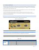
For DTE that lack RTS control, Integra-TR can operate in DOX (Data Operated Transmit) mode with only Transmit Data,
Receive Data and Ground. This 3-wire interface is shown in Figure XX.
Figure 3 - 3-wire Interface
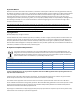
1.4.4 SETUP PORT
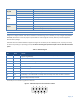
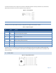
The Setup port uses a DE-9 female connector configured as DCE. Signals are described in Table 3.
Table 3 - Setup Port Signals
Pin
Name
Function
1
DCD
Tied directly to DTR
2
RXD
Data from Integra-TR to setup PC
3
TXD
Data from setup PC to Integra-TR
4
DTR
Tied directly to DCD
5
GND
Signal and chassis ground
6
DSR
Output: always positive (asserted)
7
RTS
Tied to CTS
8
CTS
Tied to RTS
9
RI
Not internally connected, reserved
The Setup port uses a proprietary communications protocol designed to work with the Integra-TR Field Programming
Software program. It is also designed to provide alpha numeric (ASCII) diagnostics information when connected to a PC
terminal emulator.
1.5 REAR PANEL
Figure 4 - Integra-TR Rear Panel