
User's Manual

Page | 8
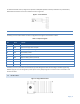
CS/SYN
Off
No RF RX carrier
Green
Receive carrier present
Red
(Reserved)
RX/TX
Off
No RF RX carrier
Green
Receiving network data
Yellow
Synthesizer unlocked
Red
Transmitter is on
RD/TD
Off
Idle
Green
RX data outgoing from RS-232 port
Red
TX data incoming at RS-232 port (or Buffered in CSMA Mode)
1.4.3 COM PORT
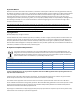
Integra-TR is configured as DCE. DTE devices should be connected using a nine-conductor pin-to-pin straight cable (PN 697-
4008-408). Some RTUs or PLCs may require a special cable to route the signals correctly. Refer to your data equipment
documentation package.
DTE baud rates from 1200 to 19200 are supported. Integra-TR's are factory set for or 9600 b/s, 8 bits, no parity, and 1 stop
bit. Unless required by your operating protocol, we advise restricting port speed to be equal to or less than the RF network
speed.
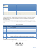
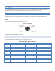
Table 2 - COM Port Signals
Pin
Name
Function
1
DCD
Output: Always asserted or asserted when receive RF carrier present (selectable via Field
Programming Software)
2
RXD
Output: Data from Integra-TR to DTE
3
TXD
Input: Data from DTE to Integra-TR
4
DTR
Input: Ignored
5
GND
Signal and chassis ground
6
DSR
Output: always positive
7
RTS
Input: Used as a “begin transmission” signal in RTS mode
8
CTS
Output: Used for handshaking in RTS mode and used for flow control in DOX mode RTS mode: RTS
to CTS delay in 4 ms DOX mode: CTS always asserted except when data overflow is detected
9
RI
Not internally connected, reserved
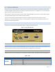
The DE-9F pin out is shown in Figure 2 for reference.
Figure 2 - COM and Setup Port Connectors Pin Locations
5 4 3 2 1
9 8 7 6