
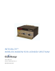
User Manual


Integra-TR User Manual Page | 9
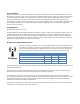
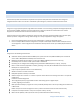
2.3 PART NUMBER BREAKDOWN
The following table provides a breakdown of the Integra-TR part number.
Table 1- Integra-TR Part Number Breakdown
242-40W8-XYZ*
W
X
Y
Z (UHF Units)
1 VHF
0 406.1-422 MHz
0 6.25 kHz
0 406.1-422 MHz,
or Dual Band
4 UHF
1 380-400 MHz
1 12.5 kHz
1 414-430 MHz
9 900 MHz
2 403-419 MHz
3 25 kHz
3 419-435 MHz (UHF), 406.1-440 MHz (UHF Dual Band)
5 Dual Band
12.5 & 25 kHz
4 132-150 MHz (VHF), 435-451 MHz (UHF)
5 450-470 MHz (UHF), 440-476 MHz (UHF Dual Band),
928-960 MHz (900 MHz)
6 150-174 MHz (VHF), 464-480 MHz (UHF)
7 480-496 MHz
8 496-512 MHz
*An F should follow any part number to designate an Integra-TR with the cooling fan option.
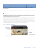
2.3.1 TRANSCEIVER IDENTIFICATION
The transceiver identification is a random, unique serial number (SN) printed on the box label and model label
on the side of the Integra-TR unit.
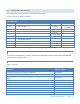
2.3.2 ACCESSORIES AND OPTIONS
Table 2 - Accessories
Accessory
DRL Part Number
Integra-TR Field Programming Kit includes software, technical manual on CD ROM with
programming cable (DRL part number 697-4008-408)
250-4008-001
SMA to Type N-Male Adapter Cable
697-5000-101
Integra-TR Start-Up Disc includes Field Programming Software, Manual and Quick Start
Guide
002-4008-100
*Cooling fan - factory option (For extended duty-cycle transmit applications)
Catalog number plus “F” suffix.
Power cable
697-4008-001
Factory Mutual NI Kit
023-1000-200
Switching Power Converter (SPC)
250-0300-133
Demo Power Kit
250-0300-175
Data Interface Kit
250-0045-103
Data Diagnostic Kit
250-0005-105