
User's Manual

NETWORK TROUBLESHOOTING
4-3
Part No. 001-4090-101/102
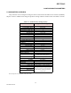
4.4 LINK TEST
Tests the network data link status by sending a number of transmissions to a remote unit, back from the
remote, computing a ratio of good to bad signals received and displaying the result as a link quality for both
individual links as well as the overall link.
Caution: Shut down your application before pressing “Link Test”.
Before starting a Link Test:
1.Ensure that the Radio Source selected is “Remote”.
2.Click in the active Short ID field and enter the address of the desired remote unit.
3. Press the “Link Test” button to start transmitting blocks of data.
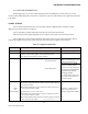
The selected remote decodes and returns data blocks. Transmission will continue until the link test button
is pressed again or after 100 data blocks are transmitted. The sent and received data are compared and the ratio of
good to bad blocks are calculated. The error rate is calculated separately for each direction and for the link as a
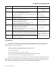
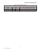
whole. The results are displayed on the message screen in the format detailed in Table 4-2.
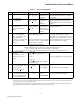
Temp Internal case temperature Operating limits:
-30 degrees C to
+75 degrees C
SWB+
Selected unit main DC power measured in tenths of a volt from 6.0
to 18.8 volts, WARNING: Do not exceed 16Vdc.
Application of more than 16 VDC will damage the unit and is not
covered by the warranty.
Should nominally be close to
13.3VDC
Operating limits:
10.0 to 16.0 V
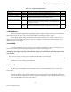
Peak
Demodulated signal voltage: peak-to-peak
(Available only for Offline Get Stats)
See transmit deviation tables
Ext1
User-specified “Analog 1" input as a voltage be-tween 0 and 10
volts DC in tenths, at 8 bits of resolution.
(Available only for Offline Get Stats)
If the “Fan Control” (Analog 1) box is checked in the RSS
program, the value displayed will be 00.0 Volt
0 to 10.0 VDC
Ext2
User-specified “Analog 2" input as a voltage be-tween 0 and 10
volts DC in tenths, at 8 bits of resolution.
(Available only for Offline Get Stats)
If the “Rx/Tp (Analog 2) box is checked in the RSS program, the
value displayed will be 00.0 Volt
0 to 10.0 VDC
Good
Number of correctly decoded transmissions in the last 15 received
In multiple frequency networks (duplex), this ratio will be an aggre-
gate of all stations heard. In single frequency networks (simplex),
this ratio usually represents receptions from the master station.
15/15 equals 100% Lower
values (8/15), coupled with
strong received signals (Remote
RSSI), usually mean local
interference at the remote site.
Total
Used with the number in the field “Good” to establish a percentage
indicative of reception quality.
Field Name Description Tolerance