
User's Manual

FEATURES AND OPERATION
2-4
Part No. 001-4090-101/102
2.2.7 SETUP PORT
The Setup port uses a DE-9 female connector configured as DCE. Signals are described
Table 2-4.
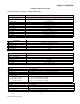
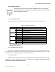
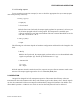
Table 2-3 Setup Port Signals
The Setup port uses a proprietary communications protocol designed to work with the Integra-H
RSS and RDS programs. It is also designed to provide numeric diagnostics information when connected
to a PC terminal emulator. (See section 2.5.1.2 for diagnostics format.)
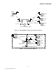
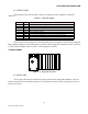
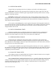
2.3 REAR PANEL
Figure 2-4 Integra-H rear panel
2.3.1 HEAT SINK
The rear panel heat sink is essential for proper operation of the Integra-H transmitter. The unit
must be mounted in a location that permits free air circulation past the heat sink. Cooling will be best if
the fins are vertical.
Pin Name Function
1 DCD Tied directly to DTR
2 RXD Data from Integra-H to setup PC
3 TXD Data from setup PC to Integra-H
4 DTR Tied directly to DCD
5 GND Signal and chassis ground
6 DSR Output: always positive (asserted)
7 RTS Tied to CTS. Also monitored to “wake up” unit from sleep mode
8 CTS Tied to RTS
9 RI Not internally connected, reserved