
User's Manual

FEATURES AND OPERATION
2-3
Part No. 001-4090-101/102
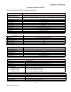
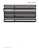
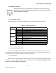
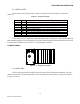
Table 2-2 COM Port Signals
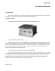
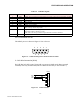
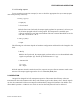
2.2.4.1 Connector Pin out
The DE-9F pin out is shown in Figure 2.2 for reference.
Figure 2-2 COM and Setup Port Connectors Pin Locations
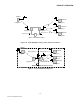
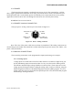
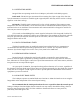
2.2.4.2 Wire Connection (DOX)
For DTE that lack RTS control, Integra-H can operate in DOX mode (Data Operated
Transmit) with only Transmit Data, Receive Data and Ground (“3-wire interface”).
Figure 2-3 3-Wire Interface
Pin Name Function
1 DCD Output: Always asserted or asserted when receive RF carrier present (selectable via RSS)
2 RXD Output: Data from Integra-H to DTE
3 TXD Input: Data from DTE to Integra-H
4 DTR Input: Ignored
5 GND Signal and chassis ground
6 DSR Output: always positive
7 RTS Input: Used as a “begin transmission” signal in RTS mode
Will “wake up” unit in sleep mode
8 CTS Output: Used for handshaking in RTS mode and used for flow control in DOX mode
RTS mode: RTS to CTS delay in 4 ms
DOX mode: CTS always asserted except when data overflow is detected
9 RI Not internally connected, reserved
12345
6789
1
2
3
4
5
6
7
8
9
R
X
D
TXD
GND
DE-9
M