
User's Manual

SECTION 2
2-1
001-4090-101/102
FEATURES AND OPERATION
2.1 OVERVIEW
This chapter describes the connections, indicators, and operating characteristics of the Integra-H.
This chapter is intended for system application and installation personnel.
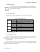
2.2 FRONT PANEL
The various front panel elements are described in the following sections.
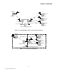
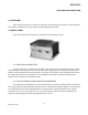
Figure 2-1 Integra-H Front Panel
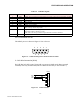
2.2.1 ANTENNA CONNECTOR
Antenna connector is a female 50-ohm SMA- type. The Integra-H is designed to operate with an
antenna having a maximum gain of 10 dB. Antennae with a higher gain are strictly prohibited (FCC &
Industry Canada). Required antenna impedance is 50 ohms. The installer of this equipment must ensure
the antenna does not emit an RF field in excess of Health Canada limits for the general population
(Safety Code 6 available from Health Canada).
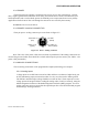
2.2.2 RF EXPOSURE COMPLIANCE REQUIREMENTS
The Integra-H is intended for use in the SCADA market. It must be mounted within a fixed RTU.
The Integra-H must be professionally installed to ensure a minimum separation distance of more than 20
cm is maintained between the radiating structure and any person. Typical installation is the antenna
mounted on a tower. (In rare instances, a 1/2 wave whip antenna is used.) In these installations, the
antenna is mounted greater than the minimum distance of 20 cm.