INTEGRA H Version Technical Manual
INTEGRA-H Copyright 2000 by DATARADIO COR Ltd. Part Number: 001-4090-101/102 Revision 0 September 2000 DATARADIO COR Ltd. designs and manufactures radios and radio modems to serve a wide variety of data communication needs. DATARADIO produces equipment for the fixed data market including SCADA systems for utilities, petrochemical, waste and fresh water management markets and RF boards for OEM applications in the Radio Frequency Data Capture market.
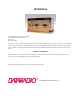
SECTION 1 PRODUCT OVERVIEW 1.1 SCOPE OF MANUAL This document provides information required for the operation and preventive maintenance of the DATARADIO COR Ltd. Integra-H Spread Spectrum Radiomodem. This manual is intended for system designers, professional installers and maintenance technicians 1.2 GENERAL DESCRIPTION Integra-H is a high-speed protocol transparent radiomodem.
PRODUCT OVERVIEW 1.2.2 ACCESSORIES AND OPTIONS Table 1-1 Integra-H Accessories and Options Accessory DRL Part Number Local RSS & RDS software kit (diskette and setup/data cable) SMA Male - BNC Female adapter cable Power cable 023-4090-005 023-3410-098 732-03273-001 (DRI p/n) For information on accessories and options, contact your sales representative. In the United States phone 1-800-992-774. For international sales, phone 1-612-882-5529 or 1-305-829-4030. 1.2.
PRODUCT OVERVIEW 1.5 REPLACEMENT PARTS This product is normally not field-serviceable, except by the replacement of complete units. Specialized equipment and training is required to repair logic boards and radio modules. Contact Technical Service for information before returning equipment. A Technical Service representative may suggest a solution eliminating the need to return equipment. 1.6 FACTORY REPAIR Dataradio products are designed for long life and failure-free operation.
PRODUCT OVERVIEW The unit is not hermetically sealed and should be mounted in a suitable enclosure when dust and/or a corrosive atmosphere are anticipated. Physically, there are no external switches or adjustments. All operating parameters are set using the INTRSS software program. 1.8 DIAGNOSTICS Integra-H has sophisticated built-in diagnostics that may be transmitted automatically without interfering with normal network operation. In addition, commands to generate test transmissions, etc.
PRODUCT OVERVIEW FCC/IC Rule: The output power is not to exceed 1.0 watt and the EIRP not to exceed 6 dBW if the hopset uses 50 or more frequencies. A sample calculation is provided below.
PRODUCT OVERVIEW 1.11 NETWORK APPLICATION Integra-H is suited to a variety of network applications. Its primary design goal satisfies the needs of SCADA systems using RTUs, PLCs, or other similar equipment in either point-to-point or point-to-multipoint service. This section gives an overview of some common configurations. Selection of “master” or “remote” as well as data delivery conditions is done using INTRSS. 1.11.
PRODUCT OVERVIEW 1.11.3 COMMON CHARACTERISTICS The networks described in this section share common characteristics: 1.The network speed (9600, 19200, 21400, and 25600 b/s) must be the same for all stations in a network. 2.Transmission of online diagnostics may be enabled or disabled at any station or stations without affecting their ability to communicate with other stations. 1.11.4 POINT-TO-POINT SYSTEM A simple point-to-point connection is shown in Figure 1-3.
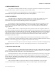
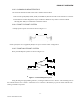
PRODUCT OVERVIEW 1.11.6 EXTENDING A LANDLINE (TAIL CIRCUIT) Integra-H may be used to extend a landline circuit (giving access to difficult locations, etc.). This type of connection is called a “tail circuit” and is shown in Figure 1-5. The tail circuit assembly may be used in any of the network types described in the preceding sections. Integra-H Figure 1-5 Landline (Tail Circuit) Note: The phone-line modems should be full duplex units.
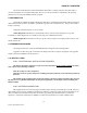
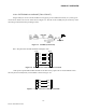
PRODUCT OVERVIEW Master Remote Integra-H Integra-H Remote Integra-H Integra-H Integra-H Remote RS-232 Serial RS-232 Serial Integra-H Store and Forward Device Figure 1-8 Point-Multipoint Using a Store and Forward Device Master Hop Sequence 1 Hop Sequence 2 Integra-H Remote Integra-H A Remote B Integra-H Integra-H Integra-H Remote Integra-H Data line harness (RS232 Serial) Figure 1-9 Point-Multipoint (Repeater) 1-9 Part No.
PRODUCT OVERVIEW GENERAL SPECIFICATIONS These specifications are subject to change without notice.
PRODUCT OVERVIEW Setup/Diag Port Data Format Data Rate Analog Inputs Interface Proprietary binary for setup, ASCII for diagnostics 9600 b/s, 8 bit, no parity, 1 stop bit Two inputs, 0-10 VDC, 8 bits. May be read only via offline diagnostics. Absolute maximum input voltage < 20 Vdc. Inputs are reverse-voltage protected.
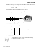
SECTION 2 FEATURES AND OPERATION 2.1 OVERVIEW This chapter describes the connections, indicators, and operating characteristics of the Integra-H. This chapter is intended for system application and installation personnel. 2.2 FRONT PANEL The various front panel elements are described in the following sections. Figure 2-1 Integra-H Front Panel 2.2.1 ANTENNA CONNECTOR Antenna connector is a female 50-ohm SMA- type. The Integra-H is designed to operate with an antenna having a maximum gain of 10 dB.
FEATURES AND OPERATION 2.2.3 SAFETY NOTICE The Integra-H uses low power radio frequency transmitters. The concentrated energy from an antenna may pose a health hazard. People should not be in front of the antenna when the transmitter is operating. 2.2.4 LED INDICATORS Integra-H has four two-color LED indicators. Their functions are shown in Table 2-1.
FEATURES AND OPERATION Table 2-2 COM Port Signals Pin Name Function 1 2 3 4 5 6 7 DCD RXD TXD DTR GND DSR RTS 8 CTS 9 RI Output: Always asserted or asserted when receive RF carrier present (selectable via RSS) Output: Data from Integra-H to DTE Input: Data from DTE to Integra-H Input: Ignored Signal and chassis ground Output: always positive Input: Used as a “begin transmission” signal in RTS mode Will “wake up” unit in sleep mode Output: Used for handshaking in RTS mode and used for flow control
FEATURES AND OPERATION 2.2.7 SETUP PORT The Setup port uses a DE-9 female connector configured as DCE. Signals are described Table 2-4. Table 2-3 Setup Port Signals Pin Name Function 1 2 3 4 5 6 7 8 9 DCD RXD TXD DTR GND DSR RTS CTS RI Tied directly to DTR Data from Integra-H to setup PC Data from setup PC to Integra-H Tied directly to DCD Signal and chassis ground Output: always positive (asserted) Tied to CTS.
FEATURES AND OPERATION 2.3.2 POWER The Integra-H power requires a regulated power source of 13.3 VDC nominal (10 - 16 VDC max.) negative ground with a minimum 2.0 A rating. An internal surface-mount 3A modem fuse (not field-replaceable) and a crowbar diode protect the main RF power components from reverse polarity. Application of more than 16 VDC will damage the unit and is not covered by the warranty. WARNING: Do not exceed 16Vdc. 2.3.
FEATURES AND OPERATION 2.3.4.2 Analog outputs To use an analog connection as output, be sure to check the appropriate box (in the RSS program under Settings/Analog Connector) : 1. Analog 1 (green) a. Input (or) b. Fan Control With the Fan Control selected, the output signal regulates fan operation. It is factory set for all units equipped with the cooling option. The temperature-controlled opencollector transistor is rated 100 mA maximum.
FEATURES AND OPERATION 2.4.1 OPERATING MODES Integra-H has two operating modes for its COM port: (selectable via the RSS program) DOX mode: The RS-232 port is monitored for incoming data. Upon receipt of the first data byte, the transmitter is turned on. The RTS signal is ignored (Note: RTS may still be used as a wakeup signal for a unit that is asleep). RTS mode: The RTS signal is monitored for a low-to-high transition. This transition causes Integra-H to turn on its transmitter.
FEATURES AND OPERATION The COM port will support 7 or 8 data bits, one or two stop bits, and even, odd or no parity. Selection is made via the Radio Service Software (RSS). These parameters may be set differently on various Integra-H units without affecting their ability to communicate with each other. 2.4.
FEATURES AND OPERATION Where user applications require continuous data transmission from a master unit, diagnostics are delivered locally to its own setup port regardless of the Online Diagnostics setting at the start of each data transmission and also at intervals of 20 seconds. If user-enabled, diagnostics are also sent on the network but only at the start of the first data transmission. Reception of online diagnostics is always enabled and is delivered out at the Setup Port in an ASCII form.
FEATURES AND OPERATION within itself is a constant length, but the fields are not all uniform in length. Field definitions are shown in Table 2-4. Table 2-4 Online Window Field Definition Name Length (in bytes) Short ID Temperature B+ Remote RSSI Local RSSI FWD Power Rev Power 4 3 4 4 4 4 1 Rx Quality 3 3 Description 1 - 254 Signed value From 6.0 to 18.8 V Signal strength received by remote station in dBm Signal strength for this remote as received by local station in dBm From 0.
FEATURES AND OPERATION 2.5.2.3 B+ Voltage Current value of supply voltage. SWB+ is a 4-digit value in volts, e.g. a value of 13.3 indicates 13.3 VDC. This value should remain within the limits of 10-16 VDC ±2%. 2.5.2.4 Remote RSSI Displays the strength of the last valid data signal received by a reporting remote unit. In a polling type network, the last signal usually originates from the polling master unit.
FEATURES AND OPERATION 2.5.2.7 Forward Power Approximate measure of transmit power. This is a 4-digit value in watts rounded to the nearest tenth. Note that this is an approximate value that should be used for trend monitoring only. It does not compare in accuracy with values obtained by a standard wattmeter. 2.5.2.8 Interpreting Power Readings The values returned are approximate and should not be regarded as an absolute indicator of performance. For example, a unit that shows a forward power of .
FEATURES AND OPERATION 2.5.2.10 Reverse Power and SWR A reverse power reading above zero is an indication that the antenna, feedline or connectors are damaged, corroded or improperly tuned. This creates standing waves that are reported as a Standing Wave Ratio (SWR). Table 2-5 is based on a forward power of 1 watt (it may be scaled for lower power settings) and gives guidelines to interpreting these figures: Table 2-5 SWR / Rev Pwr Interpretation SWR Rev Pwr 1:1 1.5:1 2:1 3:1 or greater 0 0.05 0.2 0.
FEATURES AND OPERATION 2.7 LOW POWER OPERATION To accommodate users, who operate sites with limited available power, Integra-H offers the following power saving features: lReduced transmit power mode lSleep mode lSuspend 2.7.1 REDUCED TRANSMIT POWER The Integra-H transmitter is type-approved for power levels varying from .1 to 1 Watt. Select the desired power setting using the Integra RSS. 2.7.2 SUSPEND MODE Note: As long as the RTS is asserted (on any port), the unit will be kept awake. 2.7.2.
FEATURES AND OPERATION 2.7.3 SLEEP MODE In this mode, the unit is always in low power consumption (< 20 mA). Only asserting RTS on the COM or the SETUP ports can wake-up the unit. When the unit is sleeping, it cannot detect the presence of a carrier. This mode can be selected from the RSS. The unit will be ready to receive a carrier and decode data within 45 to 65 ms (depending on radio model and temperature) after wake-up. 2.7.
FEATURES AND OPERATION Use the highest suitable port baud rate (without exceeding the radio network speed) Operating an RTU at 1200 b/s on a 9600 b/s network will increase data transmission delays and reduce system performance. Evaluate the need for online diagnostics Enabling online diagnostics increases delays by 2.5 to 10 ms (depending on speed). In critical applications, this extra delay can be eliminated by disabling online diagnostics. Offline diagnostics (diagnostics on request) remain available.
SECTION 3 MAINTENANCE AND ADJUSTMENTS 3.1 OVERVIEW AND MAINTENANCE INTERVALS This chapter outlines the basic tests and adjustments required upon initial installation and thereafter at annual maintenance intervals or whenever deterioration in performance indicates that adjustment may be required. Units are delivered from the factory properly aligned and tested on the frequency range specified at time of order.
MAINTENANCE AND ADJUSTMENTS 3.5 PRELIMINARY STEPS Important Note: Before proceeding make sure that the service monitor has been calibrated recently and has warmed up for at least the time specified by its manufacturer. Some reported frequency and deviation problems have actually been erroneous indications from service monitors that have not adequately warmed up. This is particularly likely when field service is done during winter months. 1.
MAINTENANCE AND ADJUSTMENTS Table 3-7 Tests and Adjustments Step 1 Action Expected Results Measure With Output Power 1W 1 + 5%, -20% 2 Frequency Error Press TX Unmod Within + 300 Hz Adjust using the RSS Power Out setting (255 is the maximum) or refer to Factory Tech support Adjust using the RSS Freq Warp setting. (Typical adjustment range is 1.5kHz) If found outside limits, call factory technical support.
SECTION 4 NETWORK TROUBLESHOOTING 4.1 TROUBLESHOOTING OVERVIEW A Radio Diagnostic Software program is provided to help the user find problems on individual units within a network. This program is launched via the executable file INDIAG.EXE. This program runs (only) from the Integra Setup port.
NETWORK TROUBLESHOOTING 4.2.2 OFFLINE DIAGNOSTICS Offline diagnostics are used for trouble-shooting and test transmissions to remote units or to a local connected unit. Offline diagnostics are intrusive as they take control of radio channels. User applications may have to be offline. 4.
NETWORK TROUBLESHOOTING Field Name Description Tolerance Temp Internal case temperature SWB+ Selected unit main DC power measured in tenths of a volt from 6.0 to 18.8 volts, WARNING: Do not exceed 16Vdc. Should nominally be close to 13.3VDC Application of more than 16 VDC will damage the unit and is not covered by the warranty.
NETWORK TROUBLESHOOTING Table 4-2 Action Blocks Sent Blocks Received by remote Link Quality to re-mote Responses from re-mote Link Quality from remote Overall Link Quality Link Test Display Format Format Results Relation A 0-100 Records the total number of blocks transmitted to the remote B 0-100 Indicates recorded total number of blocks received by the remote 0.0% to Ratio (percentage) of blocks received by the remote compared to blocks B over A 100.0% transmitted.
NETWORK TROUBLESHOOTING Table 4-3 Typical Transmit Deviation Connected to an Integra-H, Part Number 242-4090-XY0, Native Compatibility Mode Network Speed (in b/s) 19200 9600 4800 Typical Deviation (kHz) + 8.0 + 8.0 + 8.0 Voltage at Pin 4 when receiving that deviation from other units (white wire of analog/power connector) (Vpp) 1 1 1 4-5 Part No.
SECTION 5 CONFIGURABLE PARAMETERS 5.1 PARAMETER OVERVIEW The parameters used to configure the Integra-H units are described in the Radio Service Software (INTRSS) help file. Section 5 summarizes the Integra-H parameter settings and their variations when used within a network.
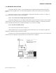
SECTION 6 CIRCUIT DESCRIPTION 6.1 OVERVIEW Section 6 describes the circuit operation of the logic board. This section is intended for use by engineering and service personnel. 6.2 CIRCUIT DESCRIPTION Refer to Figure 6-1 for the block diagram of the Integra-H Logic Board. 6.2.1 MICROPROCESSOR CIRCUIT The microprocessor contains two Z84015 CMOS low power Intelligent Peripheral Controllers (IPC). Each IPC is an 8-bit microprocessor integrated with CTC, SIO, PIO Clock Generator Controller and Watch Dog Timer.
CIRCUIT DESCRIPTION 6.2.4 TRANSMIT & RECEIVE DATA Transmit Data from the RS-232 port is level-shifted to TTL by U15 and passed through the CPU for further processing and conversion from asynchronous to synchronous format. The CPLD modem, U16, takes the digital data stream from SIO-A of the CPU and synthesizes to the constant-amplitude analog baseband signal. The synthesized data stream is filtered by U10, buffered by U9B, and applied to radio module TXA at P1-6.
CIRCUIT DESCRIPTION An 8 channel, 8-bit successive approximation A/D converter, type AD0838 (U9), is interfaced to CPU (U18) and Peripheral (U20). U19 generates a power-on reset for the CPU and U6 is a temperature sensor used by the firmware to compensate for variations in RSSI. The RSSI signal from the transceiver is amplified and filtered by U7A. The signal is compared to a threshold value set by digital potentiometer (U5A).
CIRCUIT DESCRIPTION U21 U17 BI-COLOR LED PERIPHERAL U16 CPLD MODEM CPU CONTROL BUS DATA BUS ADDRESS BUS TXC TXD PA0-PA7 U20A ,B RS-232 DRIVER USER PORT SIO-A U22 ROM SYNTHESIZER ENABLE-CLOCK-DATA RX ENABLE TX ENABLE FAST PEAK DETECT U18 DE9 Q3 EXT 1 EXT 2 RXS SLICER LEVEL RX-EN MODE SPEED U15 SETUP PORT FILTER CLOCK RXC RXD MEM. DECODE DE9 TXA CLOCK OUT RAM OUT-2 U4 U19 Q4 RESET A/D OUT 13.6 V CLK,DATA SELECT X1 19.
SECTION 7 DEFINITIONS Bit dribble COM Port CTS DCE DOX DTE EIRP Full Channel Half Channel Network speed PLC RDS Refarming RSS RTS RTS mode RTU SCADA SETUP Port Transparent Extraneous bits delivered at the end of a data transmission. Equivalent to a “squelch tail” in voice systems. Integra-H does not have bit dribble. The Communications Port of Integra-H. This port is configured as DCE and is designed to connect directly to DTE. Clear to Send.