
User Manual

GENERAL INFORMATION
1-2
June 1997
Part No. 001-3492-001
NOTE: The synthesizer must be loaded each time pow-
er is turned on. Therefore, one loader board or cus-
tomer supplied programming circuit is required for
each data transceiver.
1.2.3 DL3492 WITH MODEM
The DL3492 (Part No. 242-3492-5x0) includes
the 9600 baud Modem (Part No. 023-3276-001),
which supports the RNET™ communication proto-
col, allowing data communication between the
Johnson Data Telemetry high specification synthe-
sized products and the Motorola RNET radio/
modems.
The Modem features include:
l User Programmable Data Rates; 9600, 4800, 2400
and 1200 baud in a 25 kHz bandwidth.
l RS-232 compatible.
l Simplex or Half-Duplex operation.
l RTS-CTS handshaking protocol with option for
configuring any two units as a digital repeater.
l Supports asynchronous, serial or transparent data
formats.
l Front panel LEDs provide indication for Transmit,
Receive and Power.
l Built-In Diagnostics reported both locally and
"Over-The-Air":
Reports specific unit programming
Loopback test feature
RSSI
Forward and Reflected Power
Temperature
Supply Voltage
l 8-Channels programmable with option to switch
channels remotely "Over-The-Air".
This board is programmed using an IBM PC or
compatible computer and the RSS programming soft-
ware. The 3276 Modem Programming Kit (Part No.
023-3276-005) includes programming instructions
contained in the RSS Manual.
1.2.4 DM3492 SYNTHESIZER PROGRAMMING
The DM3492, when used without the Universal
Loader Board (Part No. 023-3240-001) requires cus-
tomer supplied circuitry to load the synthesizer with
channel information. The protocol that this circuitry
must follow is described in Section 3.
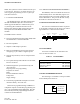
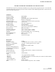
1.3 TRANSCEIVER IDENTIFICATION
The transceiver identification number is printed
on a label that is affixed to the PC board. The follow-
ing information is contained in that number:
1.4 ACCESSORIES
Accessories available for the 3492 data trans-
ceiver are listed in Table 1-1.
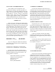
1.5 PART NUMBER BREAKDOWN
The following is a breakdown of the part number
used to identify this transceiver:
Table 1-1 ACCESSORIES
Accessory Part No.
3276 Service Manual 001-3276-001
3240 Service Manual 001-3240-001
Interface cable 023-3472-007
3492 2 A
1 4 3
A 12345
Model
Revision
Letter
Ninth Digit
of PN
Manufacture
Date
Week No.
of Year
Year
Plant
Warranty
Number
242-3492 - 5 X 0
1 = 12.5 kHz BW
5 = 928-960 MHz
3 = 25 kHz BW