
User Manual


ALIGNMENT PROCEDURE
6-4
June 1997
Part No. 001-3492-001
5. Load the synthesizer with a receive channel fre-
quency at the MIDDLE of the band.
6. Apply a -47 dBm signal from the RF signal genertor
to J501 on the radio. Adjust deviation for:
1.5 kHz with 1 kHz tone for 12.5 kHz radios
3 kHz with 1 kHz tone for 25 kHz radios.
NOTE: Maintain these deviation levels throughout the
test when measuring AC levels, SINAD and % distor-
tion, unless otherwise instructed.
7. Preset L230 for 2.5V DC ±0.05V at J201, pin 13.
8. Set RF signal generator to -105 dBm, unmodulated.
9. Set generator frequency to :
3 kHz below channel center on 12.5 kHz radios
5 kHz below channel center on 25 kHz radios
10.Adjust C223 (first) and L212 for peak RSSI voltage.
(Use 2V scale on DVM.)
11.Apply a -47 dBm signal from the RF signal genera-
tor to J501 on the radio with standard deviation lev-
els.
12.Adjust L222 for minimum distortion (psophometri-
cally weighted).
13.Set RF signal generator to -105 dBm, unmodulated.
14.Adjust L212 for peak RSSI voltage. (Use 2V scale
on DVM.)
15.Apply a -47 dBm signal from the RF signal genera-
tor to J501 on the radio with standard deviation lev-
els.
16.Adjust L230 for maximum receive audio voltage.
17.Verify that the receive audio RMS voltage is
150 mV ±50 mV.
18.Verify that the receive audio DC voltage is
2.5V ±0.3V.
19.Measure the % distortion
(spec is <3% psophometrically weighted).
20.Adjust the amplitude of the RF signal generator on
J501 until an 12 dB SINAD level (psophometrically
weighted) is reached.
21.Measure the 12 dB SINAD sensitivity. The RF
input level should be less than -116 dBm (0.35 µV).
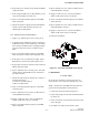
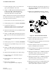
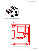
Figure 6-3 RECEIVER TEST SETUP
22.Load the synthesizer with a receive channel fre-
quency to the LOW end of the band.
23.Verify the RF generator amplitude level is less than
-116 dBm at 12 dB SINAD.
24.Load the synthesizer with a receive channel fre-
quency to the HIGH end of the band.
25.Verify the RF generator amplitude level is less than
-116 dBm at 12 dB SINAD.
26.Adjust generator RF level to -120 dBm and measure
DC (RSSI) voltage on J201, pin 12 of the radio
(spec is less than or equal to 0.90V DC).
27.Adjust generator RF level to -120 dBm and measure
DC (RSSI) voltage on J201, pin 12 of the radio
(spec is less than or equal to 0.8V DC).
28.Adjust generator RF level to -60 dBm and measure
DC (RSSI) voltage on J201, pin 12 of the radio
(spec is greater than or equal to 1.7V DC).
POWER SUPPLY
TX
RX
VOLTMETER
DC
+
-
COMMUNICATIONS
SERVICE MONITOR
DC AMMETER
+
-
ANALYZER
MODULATION
+13.3V DC
0-3A