
User Manual


ALIGNMENT PROCEDURE
6-3
June 1997
Part No. 001-3492-001
6. Repeat Step 5 for channels on the LOW and HIGH
ends of the band.
7. Power output should be 4.7-5.3W (50% duty cycle)
and current should be less than 2.5A.
8. Select a Transmit channel frequency in the MID-
DLE of the band
9. Adjust the frequency displayed on the Modulation
Analyzer to the desired channel frequency by
adjusting the TCXO (Y801).
6.6.1 MODULATION ADJUSTMENT
1. Apply a 1V, 100 Hz square wave to J201, pin 6.
2. Transmit into the modulation analyzer and observe
modulation output on the oscilloscope. The modu-
lation analyzer should not have any high pass filter-
ing selected and no less than a 15 kHz low pass
filter.
3. Select a Transmit channel frequency in the MID-
DLE of the band. The DAC value should be "125".
4. If the square wave is peaked on the edges, adjust
R818 down in value for the flattest square wave.
5. Repeat Steps 3 and 4 for channels on the LOW and
HIGH ends of the band.
6. Input a 100 Hz sinewave to J201, pin 6. The mod-
ulation analyzer should still have the 15 kHz low
pass filter selected.
7. Adjust the audio analyzer output level to achieve a
transmit deviation of:
1.5 kHz for 12.5 kHz radios or
3 kHz for 25 kHz radios.
8. Select a Transmit channel frequency at the LOW
end of the band.
9. Input a 100 Hz sine-wave and set a 0 dB reference
on the Modulation Analyzer.
10.Apply a 1 kHz sine-wave. The level should be
within ±2 dB of the reference at 100 Hz.
11.Select a Transmit channel frequency in the MID-
DLE of the band.
12.Input a 100 Hz sine-wave and set a 0 dB reference
on the Modulation Analyzer.
13.Apply a 1 kHz sine-wave. The level should be
within ±2 dB of the reference at 100 Hz.
14. Select a Transmit channel frequency in the HIGH
end of the band.
15.Input a 100 Hz sine-wave and set a 0 dB reference
on the Modulation Analyzer.
16.Apply a 1 kHz sine-wave. The level should be
within ±2 dB of the reference at 100 Hz.
17.Unkey the transmitter.
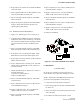
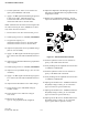
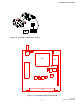
Figure 6-2 TX WITH LOADER TEST SETUP
6.7 RECEIVER
C A U T I O N
Do not key the transmitter with the generator con-
nected because severe generator damage may result.
NOTE: All distortion and SINAD measurements are
performed with psophometric audio filtering.
1. Connect the test setup shown in Figure 6-3.
2. Preset tuning slugs of L212 and L222 flush with the
top of the can.
3. Preset C223 to the center position (slot in-line with
axis of the part).
4. Re-adjust L212 and L222 clockwise 2 turns.
POWER SUPPLY
+7.5V DC
+
-
COMMUNICATIONS
SERVICE MONITOR
OSCILLOSCOPE
WATTMETER
5W, 50 OHM
DUMMY LOAD
TEST
CABLE
J201
J102
J104