
User Manual


ALIGNMENT PROCEDURE
6-2
June 1997
Part No. 001-3492-001
6.5.1 MODULATION ALIGNMENT
1. Apply a 1V, 100 Hz square-wave to J201, pin 6.
2. Transmit into the modulation analyzer and observe
modulation output on the oscilloscope. Set the
modulation analyzer high pass filtering OFF and no
less than a 15 kHz low pass filter.
3. Preset R818 to the center position.
4. Load the synthesizer with a channel frequency at
the MIDDLE of the band.
5. Adjust R818 for a flat square wave.
6. Apply a 100 Hz sine-wave to J201, pin 6. The mod-
ulation analyzer should still have the 15 kHz low-
pass filter selected.
7. Adjust the audio analyzer output level to achieve a
transmit deviation of:
1.5 kHz for 12.5 kHz BW radios
3.0 kHz for 25 kHz BW radios
8. Load the synthesizer with a channel frequency at
the LOW end of the band.
9. Input a 100 Hz sine-wave and set a 0 dB reference
on the Modulation Analyzer.
10.Apply a 1 kHz sine-wave. The level should be
within ±2 dB of the reference at 100 Hz.
11.Load the synthesizer with a channel frequency in
the MIDDLE of the band.
12.Input a 100 Hz sine-wave and set a 0 dB reference
on the Modulation Analyzer.
13.Apply a 1 kHz sine-wave. The level should be
within ±2 dB of the reference at 100 Hz.
14.Load the synthesizer with a channel frequency in
the HIGH end of the band.
15.Input a 100 Hz sine-wave and set a 0 dB reference
on the Modulation Analyzer.
16.Apply a 1 kHz sine-wave. The level should be
within ±2 dB of the reference at 100 Hz.
17.Unkey the transmitter.
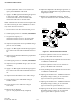
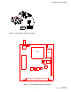
Figure 6-1 TRANSMITTER TEST SETUP
6.6 TRANSMITTER/FREQUENCY WITH
LOADER
NOTE: If the radio is not intended to use Diagnostics
go to Section 6.5.
NOTE: Subtract the current drawn by the Test Loader
or any Interface Units from all measurements.
1. Set the Diagnostic Enable DAC (DAC4) to 255,
(FFh).
2. Select a Transmit channel frequency in the MID-
DLE of the band. Make sure voltage at J201, pin 2
is 13.3V DC.
3. Adjust R535 fully clockwise for maximum power
output.
4. Adjust the Power Adjust DAC setting (DAC1) to
set the power output to 5W ±0.3W. Make sure volt-
age at J201, pin 2 is 13.3V DC.
5. Adjust voltage and power if necessary.
POWER SUPPLY
+7.5V DC
TX
RX
VOLTMETER
DC
+
-
WATTMETER5W, 50 OHM
DUMMY LOAD
COMMUNICATIONS
SERVICE MONITOR
0-1.5A
DC AMMETER
+
-
ANALYZER
MODULATION