
User Manual


6-1
June 1997
Part No. 001-3492-001
SECTION 6 ALIGNMENT PROCEDURE
6.1 GENERAL
Receiver or transmitter alignment may be neces-
sary if repairs are made that could affect tuning.
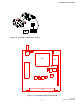
Alignment points diagrams are located in Figure 6-5
or component layouts are located in Section 8.
Fabricate test cables by referring to Figure 2-1.
This cable should include power and ground, a trans-
mit keying switch that shorts the keying line to
ground, data input and data output. The test setup
must apply the various supply voltages and load the
synthesizer with channel information.
6.2 TEST EQUIPMENT
l Modulation Analyzer, HP8901 or equivalent
l RF Signal Generator, HP8656 or equivalent
l Frequency Counter and "sniffer" probe
l Power Meter
l Oscilloscope
l Digital Multimeter
l 20 dB Attenuator
l Power Supply, HP8264A or equivalent
l Audio Analyzer, HP8903A or equivalent
l Misc. cables, connectors, attenuators.
l
6.3 INITIAL SETTINGS
1. Adjust power supply voltage to +13.3V DC.
2. Turn off the power supply.
3. Connect RF and power cables.
4. Turn on the power supply.
5. Using a DC voltmeter, monitor the DC voltage at
the junction of R812/R814 (wiper of R814), refer to
Figure 6-5.
6. Adjust R814 to 2.1V DC ±0.05V.
7. Verify the bias voltage at J201, pin 6 is +2.5V DC
±0.05V.
6.4 VCO CONTROL VOLTAGE
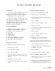
1. Connect the test setup shown in Figure 6-1.
2. Adjust R525 fully counterclockwise.
3. Load the synthesizer with the HIGHEST channel
frequency in the band.
4. Key the transmitter.
5. Verify the voltage at TP800 is < 5V DC.
6. Unkey the transmitter.
7. Load the synthesizer with the LOWEST channel
frequency in the band.
8. Key the transmitter.
9. Verify the voltage at TP800 is > 1V DC.
10.Unkey the transmitter.
6.5 TRANSMITTER AND FREQUENCY
NOTE: If the radio is intended to use Diagnostics or is
a Radio/Loader board combination go to Section 6.6.
1. Connect the test setup shown in Figure 6-1.
2. Load the synthesizer with a channel frequency in
the MIDDLE of the band.
3. Key the transmitter.
4. The voltage at J201, pin 2 should be 13.3V DC.
(Do not transmit for extended periods.)
5. Adjust R525 clockwise for 5.0W ±1W. Adjust volt-
age and power if necessary.
6. Check the power at a channel frequency on the
LOW and HIGH ends of the band. The power out-
put should be 4-6W with current less than 2.5A.