
User Manual


SERVICING
5-3
June 1997
Part No. 001-3492-001
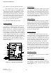
5.3.3 SECOND LO
Verify that the Second LO signal is present at
R245. The Second LO should be at 87.40 MHz and
not less than 250 mV P-P.
5.3.4 AUDIO BUFFER AMP
The Data output on J201, pin 13 should be 100-
200 mV RMS, with the preceding injection signal. If
these levels are not correct, verify proper adjustment
of L230 (see Section 6.7). The gain of U230 is 2.8 for
25 kHz radios and 5.8 for 12.5 kHz radios.
5.3.5 CRYSTAL FILTERS
The 87.85 MHz IF signal is provided to the crys-
tal filters Z220/Z221.
5.3.6 MIXER
The mixer converts the RF signal (928-960 MHz)
to 87.85 MHz. The Local Oscillator is provided by
the VCO and Q260/Q261. The level of the LO should
be approximately +3 dBm.
5.3.7 LOW NOISE AMPLIFIER (LNA)
The LNA provides approximately 12 dB of gain
at 928-960 MHz. Q200 provides active bias to Q201.
5.3.8 ANTENNA SWITCH
CR540, CR541, L544, C551 and C552 form a
Pi-network antenna switch. CR540 and CR541 are
reversed biased in Receive Mode.
5.4 TRANSMITTER SERVICING
5.4.1 SUPPLY VOLTAGES AND CURRENT
Measure the supply voltages on the following
pins of interface connector J201:
Pin 2 - 13.3V DC nominal
Pin 3 - 3-16V DC
Pin 4 - 0.0V DC (while transmitting)
Pin 5 - 3-16V DC
Pin 6 - 2.5V DC ±1%/1.5V P-P max
Place a DC ammeter in the supply line to the
transceiver and the following maximum currents
should be measured:
Pin 2 - 2.5A maximum
Pin 3 - 400 µA
Pin 5 - 400 µA
5.4.2 VCO
1. Check VCO after power splitter for power output.
(Power output should be at least -3 dBm.)
2. Check 9V Transmit (Q135, emitter).
3. If 9V is not present check Q133/Q134, U130, Q135,
Q130, Q131 and Q132 (see Section 4.4.4).
4. Check voltages on Driver Q500.
Input = 1.5V DC
Output = 3.5V DC
Power output should be at least 2 mW (+3 dBm) at
C506 (50 ohm point).
5.4.3 FINAL AMPLIFIER
1. Check the voltages on U510.
Pin 2 = 9V DC
Pin 3 = 5.0V DC (varies with power setting)
Pin 4 = 13.3V DC
Power output at C540 should be 7.5-8.0W (+38.7 to
+39 dBm).
5.4.4 ANTENNA SWITCH
1. Check the antenna switch voltages.
CR540 = 8.6V DC
CR541 = 8.0V DC
The loss through the Antenna Switch should be 1.9
to 2.1 dB.