
User Manual

GENERAL INFORMATION
1-5
June 1997
Part No. 001-3492-001
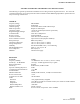
3492 UHF SYNTHESIZED TELEMETRY UNIT SPECIFICATIONS
The following are general specifications intended for use in testing and servicing this transceiver. For current ad-
vertised specifications, refer to the specification sheet available from the Marketing Department. Specifications are
subject to change without notice.
GENERAL
Frequency Range 928-960 MHz
Frequency Control Synthesized
Channel Spacing 12.5/25 kHz with 6.25 kHz Channel steps
Mode of Operation Simplex or Half Duplex
Operating Voltage +13.3V DC nominal (10-16V DC operational)
Regulated Supply Voltages +5V DC ±5%
Transmit Enable 3-16V DC at 400 µA max
Receive Current 70 mA maximum
Transceiver Enable 3-16V DC at less than 400 µA
Power and Data Connector 14-pin in-line socket (Dupont 76308-14)
RF Input/Output SMA Jack (female)
Operating Temperature -30°C to +60°C (-22°F to +140°F)
Storage Temperature -40°C to +85°C (-40°F to +185°F)
Humidity 95% maximum RH at 40°C, non-condensing
Maximum Dimensions 4.585" L, 3.25" W, 2.2" H
FCC Compliance Parts 90, 94, 15
DM3492 Customer must apply
RECEIVER
Bandwidth 32 MHz
Frequency Stability ±1.5 PPM from -30°C to +60°C (-22°F to +140°F)
Sensitivity - 12 dB SINAD ≤ 0.35 µV, -116 dBm psophometrically weighted
RF Input Impedance 50 ohms
Selectivity 65 dB 25 kHz, 60 dB 12.5 kHz
Spurious and Image Rejection 70 dB
Conducted Spurious Emissions < -57 dBm
Intermodulation 70 dB
FM Hum and Noise -40 dB, 25 kHz channels, -35 dB, 12.5 kHz channels
Receive Attack Time < 5 ms
Total Receive On Time 7 ms maximum
Audio
Distortion < 3% psophometrically weighted
Response ±1/-3 dB 0 to 2.5 kHz for 12.5 kHz Channel, 0 to 5 kHz for 25 kHz Channel
Output Bias 2.5V DC ±0.5V DC
Buffered Impedance >10k ohms
Buffered Audio Level 150 mV ±50 mV
RSSI 0.7V to 2.0V DC output from -120 to -60 dBm