3492 Synthesized 900 MHz Transceiver Service Manual First Printing June 1997 Part No. 001-3492-001 6-97mwp -1 Printed in U.S.A. April 1997 Part No.
3492 SYNTHESIZED 900 MHZ TRANSCEIVER SERVICE MANUAL Copyright 1997 by the Johnson Data Telemetry Corporation. The Johnson Data Telemetry Corporation designs and manufactures radios and radio modems to serve a wide variety of data communication needs. The Johnson Data Telemetry Corporation produces equipment for the fixed data market including SCADA systems for utilities, petrochemical, waste and fresh water management markets and RF boards for OEM applications in the Radio Frequency Data Capture market.
TABLE OF CONTENTS 1 GENERAL INFORMATION 1.1 1.2 1.3 1.4 1.5 1.6 1.7 1.8 1.9 SCOPE OF MANUAL . . . . . . . . . . . . . . . . . . . . . . . . . . . . . . . . . . . . . . . . . . . . . . . . . . . . . . . . . . . . . . . . . . . . . . . EQUIPMENT DESCRIPTION. . . . . . . . . . . . . . . . . . . . . . . . . . . . . . . . . . . . . . . . . . . . . . . . . . . . . . . . . . . . . . . . GENERAL . . . . . . . . . . . . . . . . . . . . . . . . . . . . . . . . . . . . . . . . . . . . . . . . . . . . . . . . . . .
TABLE OF CONTENTS 4.3 4.4 4.5 RECEIVER CIRCUIT DESCRIPTION . . . . . . . . . . . . . . . . . . . . . . . . . . . . . . . . . . . . . . . . . . . . . . . . . . . . . . . . 4-5 CERAMIC FILTER, RF AMPLIFIER. . . . . . . . . . . . . . . . . . . . . . . . . . . . . . . . . . . . . . . . . . . . . . . . . . . . . . . . . . . 4-5 MIXER . . . . . . . . . . . . . . . . . . . . . . . . . . . . . . . . . . . . . . . . . . . . . . . . . . . . . . . . . . . . . . . . . . . . . . . . . . . . . . . . . . .
TABLE OF CONTENTS 6 ALIGNMENT PROCEDURE 6.1 6.2 6.3 6.4 6.5 6.7 GENERAL . . . . . . . . . . . . . . . . . . . . . . . . . . . . . . . . . . . . . . . . . . . . . . . . . . . . . . . . . . . . . . . . . . . . . . . . . . . . . . . . TEST EQUIPMENT . . . . . . . . . . . . . . . . . . . . . . . . . . . . . . . . . . . . . . . . . . . . . . . . . . . . . . . . . . . . . . . . . . . . . . . . INITIAL SETTINGS . . . . . . . . . . . . . . . . . . . . . . . . . . . . . . . . . . . . . . . . . . . . . . . . . .
SECTION 1 GENERAL INFORMATION 1.1 SCOPE OF MANUAL 1.2.2 DL3492 WITH LOADER BOARD This service manual contains alignment and service information for the JDT DM3492 900 MHz Synthesized Telemetry Unit. The DL3492 (Part No. 242-3492-5x0) includes the 8-channel Loader Board (Part No. 023-3240-001), which performs synthesizer loading through an RS-232 DB-9 interface.
GENERAL INFORMATION NOTE: The synthesizer must be loaded each time power is turned on. Therefore, one loader board or customer supplied programming circuit is required for each data transceiver. 1.2.4 DM3492 SYNTHESIZER PROGRAMMING The DM3492, when used without the Universal Loader Board (Part No. 023-3240-001) requires customer supplied circuitry to load the synthesizer with channel information. The protocol that this circuitry must follow is described in Section 3. 1.2.
GENERAL INFORMATION 1.6 FACTORY CUSTOMER SERVICE 1.7 PRODUCT WARRANTY The Customer Service Department of the Johnson Data Telemetry Corporation provides customer assistance on technical problems and the availability of local and factory repair facilities. Customer Service hours are 7:30 a.m. - 4:30 p.m. Central Time, Monday - Friday. There is also a 24-hour emergency technical support telephone number.
GENERAL INFORMATION Be sure to fill out a Factory Repair Request Form #271 for each unit to be repaired, whether it is in or out of warranty. These forms are available free of charge by calling the repair lab (see Section 1.6) or by requesting them when you send a unit in for repair. Clearly describe the difficulty experienced in the space provided and also note any prior physical damage to the equipment. Include a form in the shipping container with each unit.
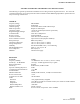
GENERAL INFORMATION 3492 UHF SYNTHESIZED TELEMETRY UNIT SPECIFICATIONS The following are general specifications intended for use in testing and servicing this transceiver. For current advertised specifications, refer to the specification sheet available from the Marketing Department. Specifications are subject to change without notice.
GENERAL INFORMATION TRANSMITTER Frequency Stability Bandwidth Maximum System Deviation Frequency Spread Modulation Wideband Data Input Bias Narrow Band Input Input Impedance Audio Distortion Audio Response Flatness RF Power Output Deviation Symmetry RF Output Impedance Duty Cycle Transmitter Adjacent Power Intermodulation Attenuation Spurious and Harmonic FM FM Hum and Noise June 1997 Part No. 001-3492-001 ±1.5 PPM from -30°C to +60°C (-22°F to +140°F) 32 MHz 5 kHz (25 kHz Channel), 2.5 kHz (12.
SECTION 2 INSTALLATION 2.1 PRE-INSTALLATION CHECKS ±3 dB that produces ±5 kHz deviation with a 1 kHz tone. When this input is used, a temperature compensated 2.5V DC bias is required as variations in voltage cause the frequency to change. The transceiver regulatory compliance must be applied for with the customer supplied modulation limiting/filter circuit and chassis. Field alignment should not be required before the 3492 is installed.
INSTALLATION 1 2 3 5 7 9 4 6 8 10 11 13 12 GROUND 14 +13.3V DC TX EN RX EN RF EN MOD IN SYNTH LOCK SYNTH EN DATA SYNTH CLOCK (1.3 MHz) DIAG EN RSSI DEMOD DIAG PART NO. 023-3472-007 Figure 2-1 DM3492 INTERFACE CABLE June 1997 Part No.
SECTION 3 PROGRAMMING A diagram of the 32 Bit Synthesizer Serial Data Stream with definitions of the bits is shown in Figure 3-1. 3.1 INTRODUCTION DM3492 - The information in Section 3.2 describes synthesizer programming protocol. This information can be used as a basis for designing the synthesizer programming hardware and software required. Clock Synth Enable D00-D23 1 MHz (max) 250 ns (min) (for D, C and B words approximately 3 ms for A0 word) D, C, B and A0 words 3.2.2 SYNTHESIZER DATA 3.
PROGRAMMING 3.2.4 C-WORD CALCULATION (24 BITS) 3.2.6 A0-WORD CALCULATION (24 BITS) The C-Word enables the auxiliary prescaler, and sets the auxiliary divide ratio for the secondary (Second LO) loop (refer to Figures 3-4 and 3-7). The A0-Word is sent last (see Figure 3-5). The A0-Word contains the data for the loop dividers and is programmed on a channel-by-channel basis.
PROGRAMMING NM3 = (INT(64 x FRAC [N ÷ 64]) ÷ 8) - 1 = (INT(64 x 0.59375) ÷ 8) - 1 = (INT(38 ÷ 8)) - 1 =4-1 =3 3.2.7 TX / RX FREQUENCY SHIFT AND BAND SELECTION As mentioned in 3.2.2, in order to implement the band selection and Rx/Rx an additional 8 bits of data are added to each of the synthesizer load words (D/C/ B/AO) (see Figure 3-1). The frequency bands and Transmit/Receive Bits are defined as follows: NM2 = 8 x FRAC [N ÷ 8] = 8 x 0.
PROGRAMMING BITS 1 1 2 0 4 1 3 0 5 0 6 0 7 0 ADDRESS 8 0 9 1 10 0 11 1 12 0 13 1 14 1 15 1 16 0 17 0 18 0 19 0 20 0 21 0 22 0 23 0 24 0 NA (AUXILIARY DIVIDE RATIO) = 437 FOR 50 kHz REFERENCE (ALWAYS 0) PA (ALWAYS 0) Figure 3-3 C-WORD BITS 1 2 3 4 5 6 7 8 9 10 11 12 13 14 15 16 17 18 19 20 21 22 23 24 1 0 0 0 0 0 0 0 0/1 0/1 0/1 0/1 0/1 0/1 0/1 0/1 0 0 0 0 0 0 1 0 ADDRESS NOT USED (ALWAYS 0000) CL CK BINARY ACCELERATION CN (CHARG
PROGRAMMING 1 A0 24 0 NF NM1 NM3 B 1 0 0 0 C 1 0 0 1 D 1 0 1 0 E 1 1 1 1 0 0 0 0 CN CK NA CL PA NR 0 NM2 PR 0 SM EM SA EA 0 0 T1 T0 PR="10" F L M O O N D G 0 1 24 ADDRESS BITS TEST BITS NOTE: E-Word not used in Synthesizer load. Figure 3-6 SERIAL INPUT WORD FORMAT XX XX XX XX XX A1 A0 Rng D7 D6 D5 D4 D3 D2 D1 D0 XX XX XX XX XX XX XX a0 Data MSB (23) LSB (00) Clock Diag En Figure 3-7 DIAGNOSTIC SERIAL DATA STREAM 3-5 June 1997 Part No.
PROGRAMMING 3.2.8 RADIO DIAGNOSTICS 3. The SYNTH ENABLE line should be held HIGH for 2 to 3 milliseconds after the last word is sent. This puts the frequency synthesizer in a SPEEDUP MODE and slightly improves lock times then the Synth Enable should be returned to a low state. The diagnostic features allow the user to program a Digital-To-Analog Converter (DAC) to adjust RF output power and modulation flatness without removing the radio from the enclosure.
PROGRAMMING 4. For quickest lock times the SYNTH ENABLE line on the last load word should be held high for 2 to 3 milliseconds. It MUST NOT be left high as the synthesizer in the SPEEDUP mode has poor noise performance and would degrade the Receive performance.
PROGRAMMING This page intentionally left blank. June 1997 Part No.
SECTION 4 CIRCUIT DESCRIPTION 4.1 GENERAL 4.1.3 RECEIVER 4.1.1 INTRODUCTION The receiver is a double-conversion type with intermediate frequencies of 87.85 MHz / 450 kHz. Bandpass filters reject the image, half IF, injection, and other unwanted frequencies. A four-pole crystal filter enhances receiver selectivity. The main subassemblies of this transceiver are the RF board, VCO board, TCXO, Loader board or Modem. A block diagram of the transceiver is located in Figure 4-1.
CIRCUIT DESCRIPTION RF BPF RF AMP RF BPF Z200 Q200/Q201 Z201 87.85 MHz MIXER Q211 CRYSTAL FILTER IF / 450 kHz FILTER Z220/Z221 U230 1st LO AMP 840.15-872.
CIRCUIT DESCRIPTION The DC voltage applied across CR823 comes from the modulation adjust control R818 on the RF board. R820 applies a DC biasing voltage to CR822; C815 provides DC blocking. RF isolation is provided by C827, R822 and R817. 4.2.1 VOLTAGE-CONTROLLED OSCILLATOR Oscillator The VCO is formed by Q820, several capacitors and varactor diodes, and ceramic resonator L826.
CIRCUIT DESCRIPTION capacitance that is multiplied. If a noise pulse or other voltage change appears on the collector, the base voltage does not change significantly because of C842. Therefore, base current does not change and transistor current remains constant. CR840 decreases the charge time of C842 when power is turned on. This shortens the start-up time of the VCO. C840 and C841 are RF decoupling capacitors. The 928-960 MHz band is divided into two segments, 928-944 MHz and 944-960 MHz.
CIRCUIT DESCRIPTION 4.2.7 SYNTHESIZER INTEGRATED CIRCUIT (U800) Impedance matching between the Z200 and RF amplifier Q201 is provided by C201, C203 and L200. CR200 protects the base-emitter junction of Q201 from excessive negative voltages that may occur during high signal conditions. Q200 is a switched constant current source which provides a base bias for Q201. Q200 base bias is provided by R200/R201.
CIRCUIT DESCRIPTION 4.3.4 CRYSTAL FILTER, FIRST IF SECTION Second IF Filter Z220 and Z221 form a 2-section, 4-pole crystal filter with a center frequency of 87.85 MHz and a -3 dB passband of 8 kHz (12.5 kHz BW) or 15 kHz (25 kHz BW). This filter establishes the receiver selectivity by attenuating the adjacent channel and other signals close to the receive frequency. C223, C224, and L221 adjust the coupling of the filter. L222, C226, C227 and R223 provide impedance matching between the filter and U230.
CIRCUIT DESCRIPTION 4.4 TRANSMITTER CIRCUIT DESCRIPTION Q520 decreases the input voltage to U510 to lower the power. The control voltage is isolated from RF by ferrite bead EP510 and C511 decouples RF. 4.4.1 DRIVER The VCO RF output signal is applied to R846, R847 and R848 that form a resistive splitter for the receive first local oscillator and the transmitter. The VCO signal is then applied to a 50 ohm pad formed by R500, R501, and R502. This pad provides attenuation and isolation.
CIRCUIT DESCRIPTION Q130, Q131 and Q132 act as switches that turn on with the RX_EN line. When J201, pin 4 goes low, Q130 is turned off, which turns on Q131 that turns on Q132. This applies +13.3V to U130 before the TX_EN line on J201, pin 3 goes high. 4.5 VOLTAGE REGULATORS 4.5.1 +9.6 AND +5.5V REGULATED The +3-16V applied on J201, pin 5 is applied to the base of Q110 turning the transistor on.
SECTION 5 SERVICING 5.1 GENERAL 5.2 SYNTHESIZER SERVICING 5.1.1 PERIODIC CHECKS 5.2.1 INTRODUCTION This transceiver should be put on a regular maintenance schedule and an accurate performance record maintained. Important checks are receiver sensitivity and transmitter frequency, modulation, and power output. A procedure for these and other tests is located in Section 6. It is recommended that transceiver performance be checked annually even though periodic checks are not required by the FCC.
SERVICING Control Voltage 5.3.2 MIXER/DETECTOR Check the DC voltage at C815 with a channel near the center of the band. If the VCO is locked on frequency, this should be a steady DC voltage near 3V. If it is not locked on frequency, it should be near the lower or upper end of its range (0V or 5.5V). Data Output Using a .01 µF coupling capacitor, inject a 87.85 MHz, 1 mV signal, modulated with 1 kHz at ±3 kHz deviation (for 25 kHz radios) ±1.5 kHz (for 12.5 kHz radios) at U230, pin 1.
SERVICING 5.3.3 SECOND LO Place a DC ammeter in the supply line to the transceiver and the following maximum currents should be measured: Verify that the Second LO signal is present at R245. The Second LO should be at 87.40 MHz and not less than 250 mV P-P. Pin 2 - 2.5A maximum Pin 3 - 400 µA Pin 5 - 400 µA 5.3.4 AUDIO BUFFER AMP The Data output on J201, pin 13 should be 100200 mV RMS, with the preceding injection signal. If these levels are not correct, verify proper adjustment of L230 (see Section 6.
SERVICING 5.4.5 MODULATION INPUT 1. Check for audio/data signals at J201, pin 6, Y800, pin 1 and A840, pin 3. 5.4.6 TCXO 1. Check Y800, pin 1 for 2.5V DC ±1%. 2. Adjust Y800 to set the transmitter to the frequency of operation. 3. If the frequency cannot be set to the frequency of operation, replace the TCXO. START MEASURE CURRENT AND VOLTAGES OK CHECK FUSES AND NO WIRE HARNESS CONNECTIONS ? YES MEASURE RF OUTPUT POWER 5 WATTS ? YES CHECK DEVIATION (SECTION 5.4.6) NO REFER TO SECTION 5.4.
SECTION 6 ALIGNMENT PROCEDURE 6.1 GENERAL 6.4 VCO CONTROL VOLTAGE Receiver or transmitter alignment may be necessary if repairs are made that could affect tuning. Alignment points diagrams are located in Figure 6-5 or component layouts are located in Section 8. 1. Connect the test setup shown in Figure 6-1. 2. Adjust R525 fully counterclockwise. 3. Load the synthesizer with the HIGHEST channel frequency in the band. Fabricate test cables by referring to Figure 2-1.
ALIGNMENT PROCEDURE 16.Apply a 1 kHz sine-wave. The level should be within ±2 dB of the reference at 100 Hz. 6.5.1 MODULATION ALIGNMENT 1. Apply a 1V, 100 Hz square-wave to J201, pin 6. 17.Unkey the transmitter. 2. Transmit into the modulation analyzer and observe modulation output on the oscilloscope. Set the modulation analyzer high pass filtering OFF and no less than a 15 kHz low pass filter. DC VOLTMETER + COMMUNICATIONS SERVICE MONITOR - 3. Preset R818 to the center position.
ALIGNMENT PROCEDURE 6. Repeat Step 5 for channels on the LOW and HIGH ends of the band. 12.Input a 100 Hz sine-wave and set a 0 dB reference on the Modulation Analyzer. 7. Power output should be 4.7-5.3W (50% duty cycle) and current should be less than 2.5A. 13.Apply a 1 kHz sine-wave. The level should be within ±2 dB of the reference at 100 Hz. 8. Select a Transmit channel frequency in the MIDDLE of the band 14. Select a Transmit channel frequency in the HIGH end of the band. 9.
ALIGNMENT PROCEDURE 5. Load the synthesizer with a receive channel frequency at the MIDDLE of the band. 20.Adjust the amplitude of the RF signal generator on J501 until an 12 dB SINAD level (psophometrically weighted) is reached. 6. Apply a -47 dBm signal from the RF signal genertor to J501 on the radio. Adjust deviation for: 1.5 kHz with 1 kHz tone for 12.5 kHz radios 3 kHz with 1 kHz tone for 25 kHz radios. 21.Measure the 12 dB SINAD sensitivity. The RF input level should be less than -116 dBm (0.
ALIGNMENT PROCEDURE J104 J201 OSCILLOSCOPE J102 TEST CABLE +7.5V DC POWER SUPPLY + - COMMUNICATIONS SERVICE MONITOR Figure 6-4 Rx WITH LOADER TEST SETUP R818 R540 J501 A840 Y800 Z231 1 Z230 L230 J201 L222 L212 R525 R814 TP800 14 C223 U510 Figure 6-5 ALIGNMENT POINTS DIAGRAM 6-5 June 1997 Part No.
SECTION 7 PARTS LIST SYMBOL NUMBER DESCRIPTION SYMBOL NUMBER PART NUMBER 3492 TRANSCEIVER PART NO. 242-3492-510 (12.5 kHz) PART NO.
PARTS LIST SYMBOL NUMBER C 249 C 250 C 251 C 252 C 253 C 261 C 262 C 263 C 264 C 265 C 266 C 267 C 268 C 269 C 270 C 500 C 501 C 502 C 503 C 504 C 505 C 506 C 510 C 511 C 512 C 513 C 514 C 515 C 516 C 517 C 518 C 520 C 521 C 522 C 523 C 524 C 526 C 527 C 528 C 529 C 530 C 531 C 533 C 534 C 540 C 541 C 542 DESCRIPTION .1 µF ±5% X7R 1206 .01 µF ±10% X7R 0603 .01 µF ±10% X7R 0603 1 µF 16V SMD tantalum .01 µF ±10% X7R 0603 22 pF ±5% NPO 0603 22 pF ±5% NPO 0603 22 pF ±5% NPO 0603 .01 µF ±10% X7R 0603 5.
PARTS LIST SYMBOL NUMBER DESCRIPTION PART NUMBER C 856 C 900 C 901 C 902 C 903 .01 µF ±10% X7R 0603 .01 µF ±10% X7R 0603 .01 µF ±10% X7R 0603 .01 µF ±10% X7R 0603 .
PARTS LIST SYMBOL NUMBER R 139 R 140 R 141 R 148 R 200 R 201 R 202 R 203 R 205 R 212 R 213 R 214 R 215 R 223 R 230 R 231 R 232 R 233 R 234 R 240 R 241 R 242 R 243 R 244 R 245 R 246 R 247 R 248 R 249 R 250 R 260 R 261 R 262 R 263 R 264 R 265 R 266 R 267 R 500 R 501 R 502 R 503 R 504 DESCRIPTION 470 ohm ±5% 0.063W 0603 3.6k ohm ±5% 0.063W 0603 5.6k ohm ±5% 0.063W 0603 10k ohm ±5% 0.063W 0603 12k ohm ±5% 0.063W 0603 39k ohm ±5% 0.063W 0603 300 ohm ±5% 0.063W 0603 39k ohm ±5% 0.063W 0603 2.2k ohm ±5% 0.
PARTS LIST SYMBOL NUMBER DESCRIPTION PART NUMBER R 848 R 849 R 900 R 901 R 911 R 912 R 913 R 914 24 ohm ±5% 0.063W 0603 24 ohm ±5% 0.063W 0603 10k ohm ±5% 0.063W 0603 10k ohm ±5% 0.063W 0603 10k ohm ±5% 0.063W 0603 47k ohm ±5% 0.063W 0603 47k ohm ±5% 0.063W 0603 1k ohm ±5% 0.
PARTS LIST SYMBOL NUMBER DESCRIPTION PART NUMBER Q 820 Q 821 Q 822 Q 823 NPN transistor NE85619 NPN transistor NE85619 NPN transistor NE85619 NPN transistor NE85619 576-0003-651 576-0003-651 576-0003-651 576-0003-651 R 820 R 821 R 822 R 823 R 824 R 825 R 826 R 827 R 830 R 831 R 832 R 833 R 835 R 836 R 840 R 842 R 843 10k ohm ±5% 0.063W 0603 100 ohm ±5% 0.063W 0603 10k ohm ±5% 0.063W 0603 10k ohm ±5% 0.063W 0603 3.3k ohm ±5% 0.063W 0603 10 ohm ±5% 0.063W 0603 150 ohm ±5% 0.063W 0603 10 ohm ±5% 0.
SECTION 8 SCHEMATICS AND COMPONENT LAYOUTS GND C TRANSISTOR AND DIODE BASING REFERENCE TABLE TRANSISTORS Part Number Basing Diagram Identification TOP VIEW B TOP VIEW E OUT 1 576-0003-636 576-0003-640 576-0006-027 576-0006-405 576-0013-032 576-0013-046 576-0013-700 576-0013-701 DIODES 523-1504-001 523-1504-002 523-1504-016 523-5005-022 1 2 4 3 1 1 1 1 G2 3 P1F U72 6D 8C BR ZR IN G1 4 C TOP VIEW TOP VIEW 1 S 2 D GND 2 B C E 4 3 C TOP VIEW 5 5 5 5 A 4D 5A 5F 5B NC 5 INTEGRATED CIRCU
SCHEMATICS AND COMPONENT LAYOUTS LOADER BOARD 023-3240-001 J104 1 SLEEP/WAKE UP PROGRAMMING 2 RX DATA CONNECTOR 3 TX DATA 4 NC 5 GROUND RF BOARD 6 PRG0 7 GROUND 8 PRG1 9 PRG2 10 GROUND 11 GROUND 242-3492-5xx P101 J1 GROUND 1 GROUND +13.3V 2 +13.
SCHEMATICS AND COMPONENT LAYOUTS TELEMETRY RF BOARD 3276 MODEM P1 J1 GROUND 1 GROUND RXD +13.3V 2 +13.
SCHEMATICS AND COMPONENT LAYOUTS Figure 8-3 TRANSCEIVER COMPONENT LAYOUT (COMPONENT SIDE VIEW) Figure 8-4 TRANSCEIVER COMPONENT LAYOUT (OPPOSITE COMPONENT SIDE VIEW) June 1997 Part No.
SCHEMATICS AND COMPONENT LAYOUTS Figure 8-5 SCHEMATIC 1 OF 2 8-5 June 1997 Part No.
SCHEMATICS AND COMPONENT LAYOUTS Figure 8-6 SCHEMATIC 2 OF 2 June 1997 Part No.
SCHEMATICS AND COMPONENT LAYOUTS C826 L826 W835 R827 L833 W840 W841 CR824 C836 R823 C831 C830 R840 C833 CR820 C862 R841 C863 R826 C840 C834 C842 R842 Q823 W838 R825 Q820 W826 L821 R843 C846 L830 R824 L820 C861 C860 L832 R833 C844 C845 C841 R830 C854 R836 R831 R832 R835 Q822 Q821 C851 C850 L831 W839 C855 C853 R834 C852 W836 W842 C835 C838 W822 L825 C827 L823 L822 C825 C821 CR821 CR822 W823 C823 R820 W833 C820 W824 W832 C824 CR823 R82
SCHEMATICS AND COMPONENT LAYOUTS This page intentionally left blank. June 1997 Part No.