
User Manual
120 10503-201 PRELIMINARY T-96S Technical Manual9
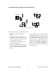
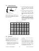
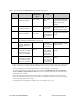
2.3.2 Interface Port
The T-96H signals are defined as DCE.
Connection to user DTE is made via a DE-
15 female connector. This connection meets
the DATARADIO Interoperability Standard
(DIOS).
Users can build a suitable cable by referring
to the connector pinout and the Interface Sig-
nal Description given in the next section. A
cable for connection to a PC AT type DE-9
connector is available from DATARADIO as
p/n 730 03267-001.
Important Note: The T96H RSS kit, used to
configure the T-96H, includes a special setup
cable, p/n 730 03266-001. Do not use this
cable to connect a user application. Doing
so will result in the T-96H switching to
“setup mode”, in which case it will not
transmit or receive user data. The green LED
flashes to indicate that the unit is in this
mode.
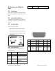
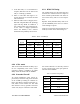
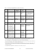
2.3.3 Interface Signal Description
B+ power (input). 10 - 16 VDC (13.3V
nominal), maximum 2 A.
RX Data. Received data from T-96H to
DTE.
TX Data. Transmit data from DTE to
T-96H.
CTS. Clear to Send. Asserted when the
T-96H is ready to accept TX Data.
RTS. Request to Send. Causes the T-
96H to transmit when asserted by the
DTE.
DCD. Data Carrier Detect. Asserted by
the T-96H when a data signal is being
received.
DTR. Data Terminal Ready. Asserted by
the T96HRSS/OFLNDIAG to select
setup mode. Do not connect to this pin
for user applications.
Test Audio. Output signal used during
adjustment and testing.
RSSI. Output signal used during testing.