
User Manual

120 10503-201 PRELIMINARY T-96S Technical Manual
9
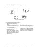
2.4 Channel Selection
Channel frequencies for 8 channels are se-
lected using the T96HRSS. Once selected,
the current operating channel may be se-
lected in one of three ways:
1.
By setting the channel on the internal
DIP switch. CS0 to CS2 on the inter-
face connector must be left discon-
nected.
2.
By strapping connections on the inter-
face connector. There is a 10KΩ pull up
resistor on each line (CS0 to CS2). The
DIP switch channel settings must be
all OFF.
3.
By selecting the channel from the
T96RSS or the OFLNDIAG programs.
The DIP switch channel settings must
be all OFF and CS0 to CS2 on the in-
terface connector must be discon-
nected (open).
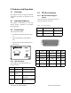
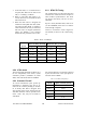
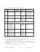
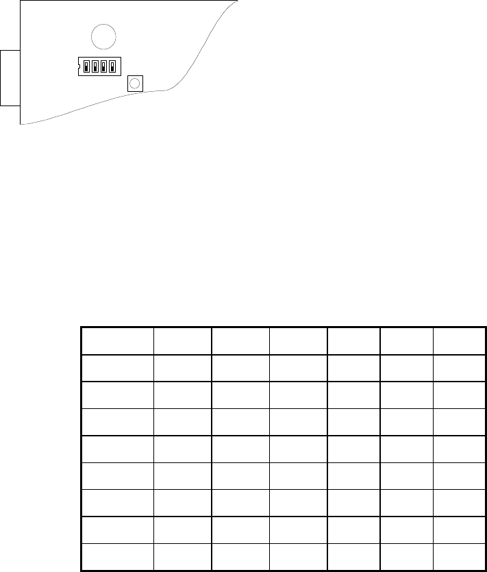
Table 2 - Channel Selection
Channel SW1-3 SW1-2 SW1-1 CS 2 CS 1 CS 0
1 on on on gnd gnd gnd
2 on on off gnd gnd open
3 on off on gnd open gnd
4 on off off gnd open open
5 off on on open gnd gnd
6 off on off open gnd open
7 off off on open open gnd
8 off off off open open open
In the table, “gnd” indicates that the pin should be connected to ground (pin 1 or 6)
2.5 Operation
The T-96H operates transparently at the
speed set using the Radio Service Software
(T96HRSS) and is designed to operate un-
attended. Basic operation is as follows.
1.
The DTE starts a data transfer by as-
serting RTS. CTS is returned after the
transmitter has been keyed and a modem
synchronization preamble sent.
See Table 3 - RTS / CTS Delays for
actual value.
2.
Data are transmitted as long as RTS is
asserted and the PTT timer, if enabled,
has not expired. RTS can be dropped
after the last stop bit of the last charac-
ter has been given to the T-96H. CTS
will be dropped when the last character
has been transmitted on the network.
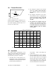
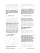
SW1
Figure 6 - DIP switch location