
User Manual

120 10503-201 PRELIMINARY T-96S Technical Manual
7
2. Features and Operation
1.1 Overview
This chapter outlines the physical features,
connections and theory of operation of the
T-96H.
2.1 Intended Audience
This chapter is intended for use by engi-
neering design, installation, and mainte-
nance personnel.
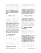
2.2 Front Panel
The front panel includes:
•
One SMA type female antenna connec-
tor.
•
Three LED indicators (described be-
low).
•
One DE-15F interface (includes power
connections)
T-96H
RX
TX
PWR
I
NTEROPERABILITY
®
D A TA T ELEM ET RY
®
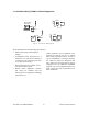
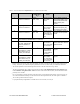
2.2.1 LED Indicators
The T-96H has three LED indicators as
shown described:
LED Indicates Description
Green Power DC Power is applied.
Flashing
green
Setup
mode
Unit is in setup mode.
Red Transmit Unit is transmitting a
data signal.
Yellow Receive Unit is receiving a data
signal.
2.3 DTE Port Interface
2.3.1 RS-232 Inteface Signal
Levels
In the descriptions of data signals, the fol-
lowing conventions are used:
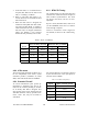
Table 1 - RS-232 Signal Levels
Term Alternates Signal level
ON asserted, spacing +3 to +15 V
OFF dropped, marking -3 to -15 V
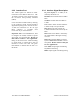
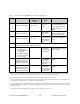
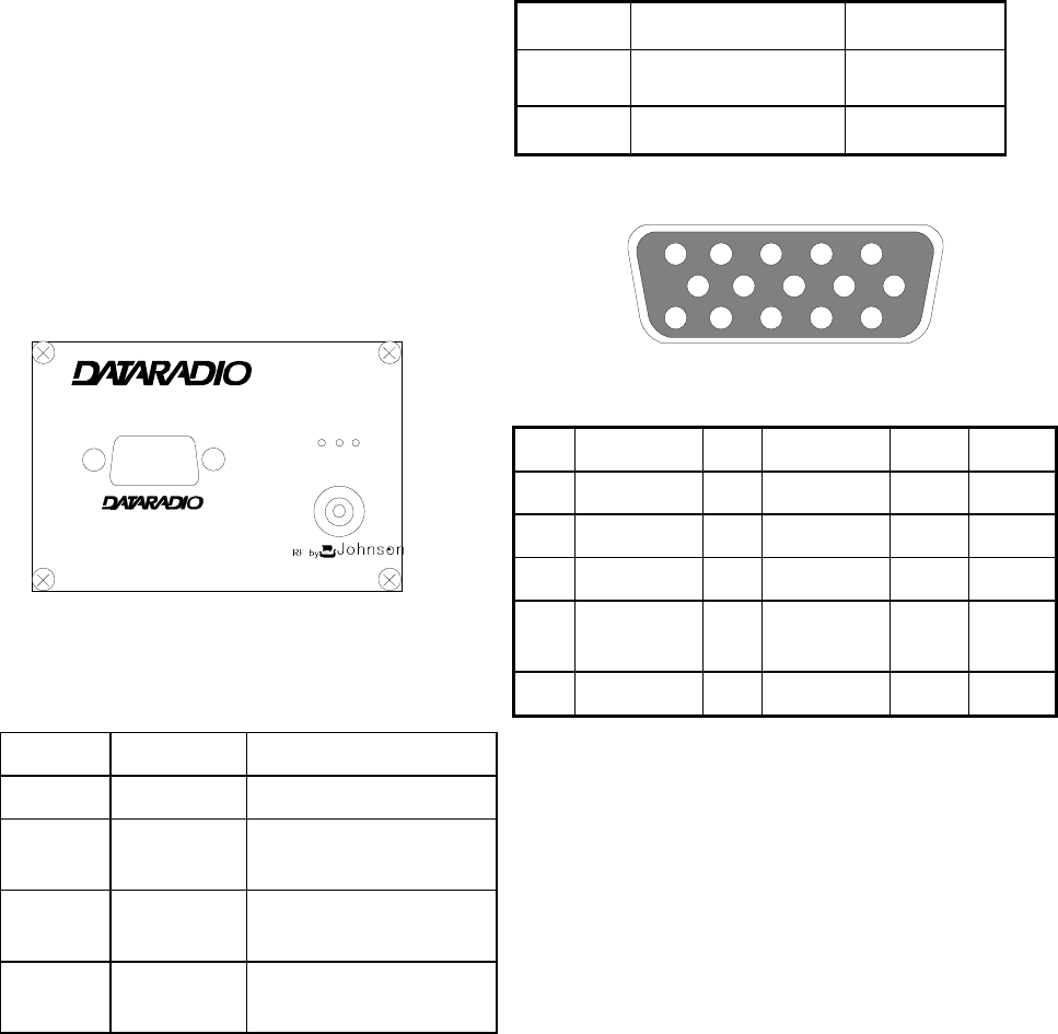
Figure 5 - Data I/O Connector Pinout
15
11
10
6
5
1
Pin
Name
Pin
Name
Pin
Name
1
Ground
6
Ground
11
CS 0
2
RX Data
7
CTS
12
CS 1
3
TX Data
8
RTS
13
CS 2
4
Test
Audio
9
DCD
14
RSSI
5
B+ Power
10
B+ Power
15
DTR