
User Manual

120 10503-201 PRELIMINARY T-96S Technical Manual12
3. Adjustments and
Maintenance
1.1 Overview
This chapter outlines the basic adjustment proce-
dures required upon initial installation and there-
after at prescribed maintenance intervals. Units
are delivered from the factory properly aligned
and tested on the frequencies specified at time of
order. Adjustment beyond that described in this
chapter is not required unless radio modules have
been tampered with or repaired. In such cases we
recommend complete factory re-alignment as
special test jigs are required.
3.1 Intended Audience
This chapter is intended for use by installation
and maintenance personnel.
3.2 Equipment Required
The adjustments described below require the fol-
lowing equipment:
• 13.3 VDC (nominal), 3A regulated power
supply.
• Radio service monitor (IFR or equivalent).
• Cable with SMA-male connector to connect
T-96H to the service monitor.
• T96H Radio Service Software (T96HRSS)
kit, including setup cable (p/n 085 03250-
xxx)
• A 486 PC (or better) to run the T96HRSS.
• Normal radio shop tools.
3.3 Maintenance Intervals
The adjustments described below should be done
once upon initial installation of the unit, and
thereafter at annual intervals or whenever a dete-
rioration in performance indicates that adjust-
ment may be required.
3.4 T96H Adjustments
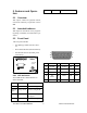
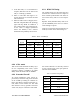
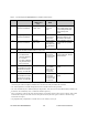
3.4.1 Preliminary Verification
Before performing any adjustments, verify the
performance of the unit as shown in the Table 5
for full channel units in the Table 6 for half
channel units.
Important Note: Before proceeding make sure
that the service monitor has been calibrated
recently and has warmed up for at least the
time specified by its manufacturer.
Some reported frequency and deviation problems
have actually been erroneous indications from
service monitors that have not adequately
warmed up. This is particularly likely when field
service is done during winter months.
3.4.2 Basic Adjustments
Basic adjustments to be performed are:
1. Transmitter power output
2. TX/RX frequency
3. Transmitter deviation
4. Demodulated audio level
These adjustments should be performed in the
sequence shown above.
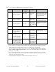
3.4.3 Tests & ajustments
Refer to the T96HRSS help file for parameter
information.
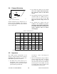
1. Connect the T-96H antenna connector to the
TX/RX input of the service monitor using a
suitable length of 50 ohm cable.
2. Connect the T-96H to a suitable power sup-
ply and adjust the supply voltage to 13.3
volts.
3. Using the setup cable (p/n 730 03266-001;
part of kit 085 03250-xxx) connect the
T-96H Data connector to the serial port of a
PC and run the T96HRSS program. This ca-
ble is required to put the T-96H into setup
mode.
4. Press GET to get the configuration of the
unit.
5. Refer to “Tests and Adjustments” tables re-
lated to the radio type (half or full channel).