
User Manual


120 10503-201 PRELIMINARY T-96S Technical Manual7
2. Features and Opera-
tion
2.1 Overview
This chapter outlines the physical features,
connections and theory of operation of the T-
96H.
2.1 Intended Audience
This chapter is intended for use by engineer-
ing design, installation, and maintenance per-
sonnel.
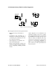
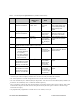
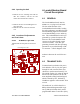
2.2 Front Panel
The front panel includes:
• One SMA type female antenna connec-
tor.
• Three LED indicators (described below).
• One DE-15F interface (includes power
connections)
T-96H
RX
TX
PWR
I
NTEROPERABILITY
®
DATA TELEMETR
Y
®
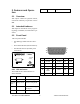
2.2.1 LED Indicators
The T-96H has three LED indicators as
shown described:
LED Indicates Description
Green Power DC Power is applied.
Flashing
green
Setup mode Unit is in setup mode.
Red Transmit Unit is transmitting a
data signal.
Yellow Receive Unit is receiving a data
signal.
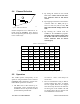
15
11
10
6
5
1
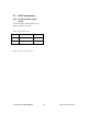
Pin
Name
Pin
Name
Pin
Name
1
Ground
6
Ground
11
CS 0
2
RX Data
7
CTS
12
CS 1
3
TX Data
8
RTS
13
CS 2
4
Test
Audio
9
DCD
14
RSSI
5
B+ Power
10
B+ Power
15
DTR