
User Manual


ALIGNMENT PROCEDURE
6-7
Part No. 001-3422-003
.
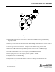
Figure 6-2 RECEIVER TEST SETUP
13.Verify that the receive audio RMS voltage is 150 mV ±50 mV.
14.Measure the % distortion (spec is <3% psophometrically weighted).
15.Adjust the amplitude of the RF signal generator on J501 until an 18 dB SINAD level (psophometrically
weighted) is reached.
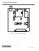
16.Adjust L221, L212, L224, L201 and L203 in turn for the best SINAD reading adjusting the generator output as
necessary to maintain an 18 dB SINAD level. DO NOT turn the slug more than 2-turns from the top of the coil.
17.Turn the slug of L221 1/2-turn clockwise. This helps to center the filter tracking across the band.
18.Measure the 12 dB SINAD sensitivity. The RF input level should be less than -116 dBm (0.35 µV).
19.Load the synthesizer with a receive channel frequency to the MIDDLE of the band.
20.Set the signal generator to the same frequency with an amplitude of -116 dBm.
21.Adjust R920 for the best SINAD reading.
22.Adjust the RF input level until 12 dB SINAD is measured. The RF input level should be less than
-116 dBm (0.35 µV).
POWER SUPPLY
+7.5V DC
POWER SUPPLY
+5V DC
+
-
TX
RX
VOLTMETER
DC
+
-
COMMUNICATIONS
SERVICE MONITOR
0-1.5A
DC AMMETER
+
-
ANALYZER
MODULATION