
User Manual


ALIGNMENT PROCEDURE
6-6
Part No. 001-3422-003
6.7 RECEIVER
C A U T I O N
Do not key the transmitter with the generator connected because severe generator damage may result.
NOTE: If the radio is intended to use Diagnostics or is a Radio/Loader board combination go to Section 6.8.
NOTE: All distortion and SINAD measurements are performed with psophometric audio filtering.
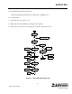
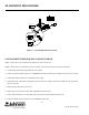
1. Connect the test setup shown in Figure 6-2.
2. Preset tuning slugs of L201, L203, L212, L221 and L224 flush with the top of the can.
3. Preset tuning slugs of L231 and L242 full clockwise and re-adjust L242 counter-clockwise 2 full turns.
4. Preset C241 to the center position (slot in-line with axis of the part).
5. Load the synthesizer with a receive channel frequency at the LOW end of the band (-21.45 MHz).
6. Apply a -47 dBm signal from the RF signal genertor to J501 on the radio. Adjust deviation for 1.5 kHz with
1.0 kHz tone for 15 kHz radios and 3 kHz deviation with 1.0 kHz tone for 30 kHz radios.
NOTE: Maintain these deviation levels throughout the test when measuring AC levels, SINAD and %
distortion.
7. Adjust R920 for 2.5V DC ±0.05V at TP281.
8. Adjust L251 for 2.5V ±0.05V at TP251.
9. Preset L253 for 2.5V DC ±0.05V at J201, pin 13.
10.Lower the RF generator 1.5 kHz for 15.0 kHz radios and 3.0 kHz for 30 kHz radios. Adjust C241 for minimum
audio distortion.
11.Reset the generator back to center frequency. Tune L231 counter-clockwise for minimum distortion. Again tune
L242 for minimum distortion.
12.Readjust L253 for minimum distortion (use 30 kHz LPF only)