
User Manual


ALIGNMENT PROCEDURE
6-4
Part No. 001-3422-003
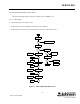
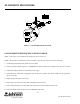
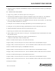
Figure 6-1 TRANSMITTER TEST SETUP
6.6 TRANSMITTER/FREQUENCY WITH LOADER
NOTE: If the radio is not intended to use Diagnostics go to Section 6.5.
NOTE: Subtract the current drawn by the Test Loader or any Interface Units from all measurements.
1. Set the Diagnostic Enable DAC (DAC4) to 255, (FFh).
2. Select a Transmit channel frequency in the MIDDLE of the band. Make sure voltage at J201, pin 2 is 13.3V DC.
3. Adjust R535 fully clockwise for maximum power output.
4. Adjust the Power Adjust DAC setting (DAC1) to set the power output to 5W ±0.3W. Make sure voltage at J201,
pin 2 is 13.3V DC.
5. Adjust voltage and power if necessary.
6. Repeat Step 5 for channels on the LOW and HIGH ends of the band.
7. Power output should be 4.7-5.3W (50% duty cycle) and current should be less than 2.5A.
8. Select a Transmit channel frequency in the MIDDLE of the band
POWER SUPPLY
+7.5V DC
POWER SUPPLY
+5V DC
+
-
TX
RX
VOLTMETER
DC
+
-
WATTMETER5W, 50 OHM
DUMMY LOAD
COMMUNICATIONS
SERVICE MONITOR
0-1.5A
DC AMMETER
+
-
ANALYZER
MODULATION