
User Manual


ALIGNMENT PROCEDURE
6-2
Part No. 001-3422-003
6.4 VCO CONTROL VOLTAGE
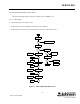
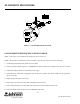
1. Connect the test setup shown in Figure 6-1.
2. Adjust R535 fully counterclockwise.
3. Load the synthesizer with the HIGHEST channel frequency in the band.
4. Key the transmitter.
5. Adjust C873 for 4.8V DC at TP831.
6. Unkey the transmitter.
7. The voltage at TP831 should be less than 4.9V.
8. Load the synthesizer with the LOWEST channel frequency in the band.
9. Key the transmitter.
10.The voltage at TP831 should be greater than .045V DC.
11.Unkey the transmitter.
12.The voltage at TP831 should be greater than 0.45V.
6.5 TRANSMITTER AND FREQUENCY
NOTE: If the radio is intended to use Diagnostics or is a Radio/Loader board combination go to Section 6.6.
1. Connect the test setup shown in Figure 6-1.
2. Load the synthesizer with a channel frequency in the MIDDLE of the band.
3. Key the transmitter.
4. The voltage at J201, pin 2 should be 13.3V DC.
(Do not transmit for extended periods.)
5. Adjust R535 clockwise for 5.0W +0.5/-0.2W. Adjust voltage and power if necessary.
6. Check the power at a channel frequency on the LOW and HIGH ends of the band. The power output should be
5W ±1W with current less than 2.5A .