
User Manual


SECTION 6
6-1
Part No. 001-3422-003
ALIGNMENT PROCEDURE
6.1 GENERAL
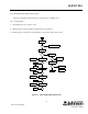
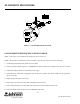
Receiver or transmitter alignment may be necessary if repairs are made that could affect tuning. Alignment
points diagrams are located in Figure 6-3 or component layouts are located in Section 8.
Fabricated test cables should include power and ground, a transmit keying switch that shorts the keying line
to ground, data input and data output. The test setup must apply the various supply voltages and load the synthe-
sizer with channel information.
6.2 TEST EQUIPMENT
l Modulation Analyzer, HP8901 or equivalent
l RF Signal Generator, HP8656 or equivalent
l Power Meter
l Oscilloscope
l Digital Multimeter
l Power Supply, HP8264A or equivalent
l Audio Analyzer, HP8903A or equivalent
l Misc. cables, connectors, attenuators.
6.3 INITIAL SETTINGS
1. Adjust power supply voltage to +13.3V DC.
2. Turn off the power supply.
3. Connect RF and power cables.
4. Turn on the power supply.
5. Apply a 2.5V DC ±0.01V level to J201, pin 6.
6. Using a DC voltmeter, monitor the DC voltage at the junction of R826/R827 (wiper of R827), refer to Figure
6-3.
7. Adjust R827 to 1.50V DC ±0.05V.
8. Monitor the DC voltage at TP801 (see Figure 6-3 for top side access to TP801).
9. Adjust R805 for 2.5V DC ±0.025V.
10.Adjust R535 fully counterclockwise.