
User Manual


SERVICING
5-6
Part No. 001-3422-003
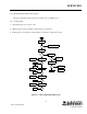
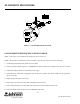
5.4.2 VCO
1. Check VCO after power splitter R894 for power output. (Power output should be at least -3 dBm.)
2. Check 9V Transmit (Q124, emitter).
3. If 9V is not present check Q124, U111, Q121, Q122, Q123, Q101 and Q102 (see Section 4.4.5).
4. Check voltages on Buffer Q501.
Input = 1.5V DC
Output = 3.5V DC
Power output should be at least 2 mW (+3 dBm) at C504 (50 ohm point).
5.4.3 PRE-DRIVER (Q511)
Check voltages on Q511.
Collector = 8.6V DC
Base = 2.2V DC
Emitter = 1.6V DC w/o RF (2.2V DC with RF)
Power output should be at least 100 mW (+13 dBm) at the junction of C517/L518 (50 ohm point).
5.4.4 FINAL AMPLIFIER (U531)
Check the voltages on U531.
Pin 2 = 5.5V DC (varies with power setting)
Pin 3 = 5.0V DC
Pin 4 = 12.7V DC
Power output at C551 should be 7.5-8.0W (+38.7 to +39 dBm).
5.4.5 ANTENNA SWITCH (CR561/CR562)
Check the antenna switch voltages.
CR561 = 8.6V DC
CR562 = 8.0V DC
The loss through the Antenna Switch should be 1.9 to 2.1 dB.