
User Manual


SERVICING
5-3
Part No. 001-3422-003
5.3 RECEIVER SERVICING
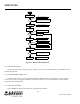
To isolate a receiver problem to a specific section, refer to the troubleshooting flowchart in Figure 5-1. Tests
referenced in the flowchart are described in the following information.
NOTE: Supply voltages are provided by the user.
5.3.1 SUPPLY VOLTAGES AND CURRENT
Measure the supply voltages on the following pins at interface connector J201:
Pin 4 - 5.0V DC Receive
Pin 5 - 5.0V DC
Place a DC ammeter in the supply line to the transceiver and the following maximum currents should be
measured:
Pin 4 - 400 µA
Pin 5 - 400 µA
5.3.2 MIXER/DETECTOR (U201)
Data Output
Using a .01 µF coupling capacitor, inject a 21.45 MHz, 1 mV signal, modulated with 1 kHz at ±3 kHz
deviation at U241, pin 1. The signal output at U241, pin 8 should be approximately 150 mV P-P.
NOTE: This signal consists of the 1 kHz modulation and harmonics of 450 kHz.
RSSI Output
The RSSI output on J201, pin 12 should be <900 mV DC with no signal applied, and >1.8V DC with a 1 mV
input signal.