
User Manual


SERVICING
5-2
Part No. 001-3422-003
When the VCO is unlocked, the f
R
and f
V
inputs to the phase detector are usually not in phase (see Section
4.1.2). The phase detector in U811 then causes the VCO control voltage to go to the high or low end of its
operating range. This in turn causes the VCO to oscillate at the high or low end of its frequency range.
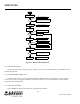
As shown in Figure 4-1, a loop is formed by VCO Q872, amplifier Q871, and the RF IN of U811. Therefore,
if any of these components begin to malfunction, improper signals appear throughout the loop. However, correct
operation of the counters can still be verified by measuring the input and output frequencies to check the divide
number.
Proceed as follows to check the synthesizer I/O signals to determine if it is operating properly.
5.2.2 REFERENCE OSCILLATOR
Check the signal at U811, pin 8. It should be 14.85 MHz for Bands 4 and 5 or 17.5 MHz for Band 6 at a level
of approximately 0.5V P-P. If the TCXO module is defective, it is not serviceable and must be replaced with a new
module as described in Section 5.1.5.
5.2.3 VCO
Output Level
The output level of Q882 can be measured with an RF voltmeter or some other type of high impedance meter.
The minimum level after a power splitter at R851 should be -3 dBm.
Control Voltage
Check the DC voltage at C815 with a channel near the center of the band. If the VCO is locked on frequency,
this should be a steady DC voltage near 3V. If it is not locked on frequency, it should be near the lower or upper
end of its range (0V or 5.5V).
Output Frequency
Check the VCO frequency at R851. If the VCO is locked on frequency, it should be stable on the transmit
channel frequency. If the VCO is not locked on frequency, the VCO control voltage is probably near 0V or 5.5V.
5.2.4 SYNTHESIZER (U811)
Lock Detector
When the VCO is locked on frequency, the lock detect output on J201, pin 7 should be high.