
User Manual


SECTION 5
5-1
Part No. 001-3422-003
SERVICING
5.1 GENERAL
5.1.1 PERIODIC CHECKS
This transceiver should be put on a regular maintenance schedule and an accurate performance record
maintained. Important checks are receiver sensitivity and transmitter frequency, modulation, and power output. A
procedure for these and other tests is located in Section . It is recommended that transceiver performance be
checked annually even though periodic checks are not required by the FCC. During the first year, make an
additional check or two to ensure no TCXO frequency drifting has occurred.
5.1.2 SURFACE-MOUNTED COMPONENTS
A large number of the components used on the transceiver board are the surface-mounted type. Since these
components are relatively small in size and are soldered directly to the PC board, care must be used when they are
replaced to prevent damage to the component or PC board. Surface-mounted components should not be reused
because they may be damaged by the unsoldering process.
5.1.3 SCHEMATIC DIAGRAMS AND COMPONENT LAYOUTS
Schematic diagrams and component layouts of the PC boards used in this transceiver are located in Section .
A component locator guide is also provided to aid in component location.
5.1.4 REPLACEMENT PARTS LIST
A replacement parts list with all the parts used in this transceiver is located in Section . Parts are listed
alphanumerically according to designator. For information on ordering parts, refer to Section 1.8.
5.1.5 TCXO MODULE NOT SERVICEABLE
The ±2.5 PPM TCXO module is not field serviceable. Part changes require a factory recalibration to ensure
that the oscillator stays within its ±2.5 PPM tolerance.
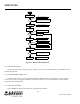
5.2 SYNTHESIZER SERVICING
5.2.1 INTRODUCTION
When there is a synthesizer malfunction, the VCO is not locked on frequency. When an unlocked VCO is
detected by the lock detector circuit, U811, pin 18 goes low (0V).
NOTE: The user-supplied circuitry must disable the transmitter and receiver when an out-of-lock condition is
indicated.