
User Manual


CIRCUIT DESCRIPTION
4-11
Part No. 001-3422-003
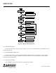
4.4.3 FINAL (U531), COMPARATOR (U111C)
RF module U531 has an RF output of 1W to 5W and operates on an input voltage from 10-16V.
Power control is provided by U581, U111, Q531 and a directional coupler A531. The power is adjusted by
Power Set Control R535 that provides a reference voltage to U111C. U111C drives Q531 and PA module U531.
One end of the Balun directional coupler is connected to a forward RF peak detector formed by R591,
CR591, C591 and U581A. The other end of the directional coupler is connected to a reverse RF peak detector
formed by R593, CR592, C593 and U581B.
If the power output of U531 decreases due to temperature variations, etc., the forward peak detector voltage
drops. This detector voltage drop is buffered by U581A and applied to inverting amplifier U111C which increases
the forward bias on Q531. The increase on Q531 increases the power output level of U531. If the power output of
U531 increases, the forward peak detector voltage increases and U111C decreases the forward bias on Q531. The
decrease on Q531 decreases the output power of U531.
The output of CR591/CR592 is fed to U581A/B respectively. If the output of either buffer increases, the
increase is applied to the inverting input of U111C. The output of U111C then decreases and Q531 decreases the
input voltage to U531 to lower the power. The control voltage is isolated from RF by ferrite bead EP532 and C531
decouples RF.
The forward/reverse power voltages from U581A/B are also applied to U913/U912 for outputs on J201.
The low-pass filter consists of L551-L554, and C552-C556. The filter attenuates spurious frequencies
occurring above the transmit frequency band. The transmit signal is then fed through the antenna switch to
antenna jack J501.
4.4.4 ANTENNA SWITCH (CR561, CR562)
The antenna switching circuit switches the antenna to the receiver in the receive mode and the transmitter in
the transmit mode. In the transmit mode, +9V is applied to L555 and current flows through diode CR561, L561,
diode CR562, and R561. When a diode is forward biased, it presents a low impedance to the RF signal;
conversely, when it is reverse biased (or not conducting), it presents a high impedance (small capacitance).
Therefore, when CR561 is forward biased, the transmit signal has a low-impedance path to the antenna through
coupling capacitor C562.
L561 and C563 form a discrete quarter-wave line. When CR561 is forward biased, this quarter-wave line is
effectively AC grounded on one end by C563. When a quarter-wave line is grounded on one end, the other end
presents a high impedance to the quarter-wave frequency. This blocks the transmit signal from the receiver. C561/
C563 match the antenna to 50 ohms in transmit and receive.