
User Manual


CIRCUIT DESCRIPTION
4-9
Part No. 001-3422-003
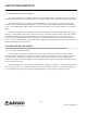
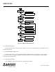
Figure 4-3 U241 Block Diagram
4.3.5 FM IF (U241)
Second LO Oscillator, Buffer (Q251)
As shown in Figure 4-3, U241 contains the second oscillator, second mixer, limiter, detector, and squelch
circuitry. The second LO oscillator is built into U241 which provides the base and emitter connections for an
internal oscillator transistor. The oscillator tank circuit consists of L251, C253 and CR251. Oscillator feedback is
provided by C254, C256 and C257. The oscillator frequency is adjusted by applying a control voltage across
R253 to CR251. The control voltage is provided by the charge pump of the auxiliary synthesizer in U811.
The emitter of the oscillator transistor is connected to the common collector buffer amplifier Q251 by C251.
R257-R259 and R254 provide bias for Q251. R254 additionally provides an RF load to decrease the buffer level.
C258, C259 and L252 filter the unwanted harmonics from the oscillator output. The output of Q251 is coupled to
the auxiliary synthesizer phase detector by C814. The oscillator is phase locked at 21.9 MHz with L251 adjusted
to center the control voltage.
Second IF Filter
The output of the internal double-balanced mixer is the difference between 21.45 MHz and 21.9 MHz which
is 450 kHz. This 450 kHz signal is fed out on pin 3 and applied to second IF filters Z241 and Z242. These filters
have passbands of 9 kHz (15 kHz BW), or 20 kHz (30 kHz BW) at the -6 dB points and are used to attenuate
wideband noise.
1
2
4
MIXER
5
15
14
11
RSSI
52.95 MHz
C234
C267
20
OSCILLATOR
52.5 MHz
+
-
RSSI OUTPUT
9
V
REG
6
V
CC
7
8
+
-
10
QUAD
AUDIO OUTPUT
L253
12
13
3
NC
LIMITER IN
LIMITER
IF AMP OUT
IF DEC1
IF DEC2
IF AMP IN
MIXER OUT
LIMITER DEC1
LIMITER DEC2
LIMITER OUT
IF AMP
16
17
18
19
RSSI FB
AUDIO FB