
User Manual


CIRCUIT DESCRIPTION
4-5
Part No. 001-3422-003
Frequency Control and Modulation
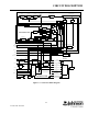
The VCO frequency is controlled in part by DC voltage across varactor diodes CR852, CR853 and CR854.
As voltage across a reverse-biased varactor diode increases, its capacitance decreases. Therefore, VCO frequency
increases as the control voltage increases. CR852/CR853 and CR854 are paralleled varactors to divide the
capacitance and improve linearity. The varactors CR852/CR853 are biased at -2.0V so the control line voltage can
operate closer to ground. CR854 is pin shifted in when transmitting to increase the VCO gain in transmit. The
control line is isolated from tank circuit RF by choke L852/L853. The amount of frequency change produced by
CR852/CR853/CR854 is controlled by series capacitor C854.
The -2.0V applied to the VCO is derived from the TCXO frequency that is amplified by Q902, rectified by
CR902 and filtered by C912, C917, C918 and C920 and loaded by resistor R919 on the RF board.
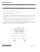
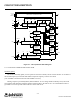
The VCO frequency is modulated using a similar method. The transmit audio/data signal from J201, pin 6 is
applied across varactor diode CR861 which varies the VCO frequency at an audio rate. Series capacitors C855/
C856 set the amount of deviation produced along with CR862 and C865. R863 provides a DC ground on the
anodes of CR861/CR862, and isolation is provided by R862 and C863.
The DC voltage across CR862 provides compensation to keep modulation relatively flat over the entire
bandwidth of the VCO. This compensation is required because modulation tends to increase as the VCO
frequency gets higher (capacitance of CR852/CR853/CR855 gets lower). CR862 also balances the modulation
signals applied to the VCO and TCXO. The D/A Converter U911 can be programmed to apply a compensating
voltage to CR862 to adjust the modulation sensitivity between the TCXO and VCO.
The DC voltage applied across CR862 comes from the modulation adjust control R827 on the RF board.
R826 applies a DC biasing voltage to CR862; C821 provides DC blocking. RF isolation is provided by C865 and
R862.
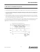
4.2.2 VCO AND REFERENCE OSCILLATOR MODULATION
Both the VCO and reference oscillator (TCXO) are modulated in order to achieve the required frequency
response. If only the VCO was modulated, the phase detector in U811 would sense the frequency change and
increase or decrease the VCO control voltage to counteract the change (especially at the lower audio frequencies).
If only the reference oscillator frequency is modulated, the VCO frequency would not change fast enough
(especially at the higher audio frequencies). Modulating both VCO and reference oscillators produces a flat audio
response. Potentiometers R825 and R827 set the VCO modulation sensitivity so that it is equal to the reference
oscillator modulation
sensitivity.