
User Manual


PROGRAMMING
3-9
Part No. 001-3422-003
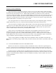
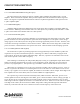
3.3 RECEIVE TO TRANSMIT SEQUENCE
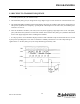
1. Load the synthesizer (D, C, B and A0 words).
2. The RX Enable (J201, pin 4) is changed from a logic high to logic low after the last bit of the A0 Word is sent.
3. The SYNTH ENABLE (SYNTH_EN) should be held in a high state for 3 milliseconds after the A0 Word is sent.
This puts the synthesizer in a temporary “speedup mode” which improves lock times. Then, the SYNTH_EN is
returned to a low state.
4. After the A0 Word is strobed in, wait 7ms (worst case) before applying a logic high to the 7.5 TX
1
line (J201,
pin 3). This allows the synthesizer to attain lock. NOTE: The lock detect line (J201, pin 7) should be monitored
and in a lock (logic high) state before enabling the transmitter.
1
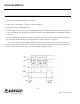
A "ramp-up/-down" circuit should be employed on the Loader to minimize adjacent channel interference caused
by the spectral spreading that occurs when a transmitter is suddenly switched on or off. The ramped voltage is
applied to the 7.5 TX line (J201, pin 3). The ramp should be approximately 3 ms.
Figure 3-4 Rx to Tx TIMING DIAGRAM
“D WORD” “B WORD” “A” WORD