
User Manual

PROGRAMMING
3-4
Part No. 001-3422-003
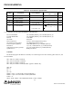
3.2.3 GENERAL RADIO PROGRAMMING PARAMETERS
Receive Bandwidth: 132-150 MHz (Band 4), 150-174 MHz (Band 5, 6)
Transmit Bandwidth: 132-150 MHz (Band 4), 150-174 MHz (Band 5, 6)
First IF: 21.45 MHz
Second IF: 450.0 kHz
First LO injection: 153.45 to 195.45 (high side injection)
Second LO injection (LO2): 21.9 MHz (high side injection)
TCXO Frequency (FREF): 14.85 MHz (Band 4, 5), 17.50 MHz (Band 6)
Resolution: 7.5, 6.25, 5.0 kHz (Band 4, 5), 2.5 kHz (Band 6)
Comparison Frequency (FCM): 37.5, 50, 25 kHz (Band 4, 5), 20 kHz (Band 6)
Synthesizer IC: Phillips SA7025A
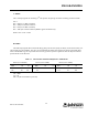
D-WORD
The D-Word programs the Reference dividers, sets enable flags for the main auxiliary phase detectors, and
sets the modulus.
NR = 396 (for 7.5 kHz resolution)
NR = 297 (for 6.25 kHz resolution)
NR = 594 (for 5.0 kHz resolution)
NR = 875 (for 2.5 kHz resolution) NOTE: applies to Band 6 only.
SM = 00
EM = 1
EA = 1
SA = 00
FMOD = 0 (for 7.5 and 5.0 kHz resolution) Modulo 5
FMOD = 1 (for 6.25 and 2.5 kHz resolution) Modulo 8
LONG = 0
Where: FCM = FREF ÷ NR and RESOLUTION = FCM ÷ FMOD
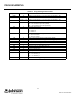
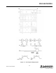
Table 3-2 Serial Interface Specifications
Symbol Parameter Test Conditions
Limits
MIN TYP MAX
Units
fCLOCK Clock Frequency 10 MHz
t
SU Set-up time: DATA to CLOCK
CLOCK to STROBE
30 ns
t
H Hold Time: CLOCK to DATA 30 ns
t
W Pulse width; CLOCK
Pulse width; STROBE B, C, D words
30
30 ns
t
SW Pulse width; STROBE
A word, PR = "01"
A word, PR = "10"
1 . (NM2 . 65) +
t
W
f
VCO
1 . [(NM2 . 65) + (NM3 + 1 . 72] +
t
W
f
VCO
ns