
User Manual


3-12
Part No. 001-2100-101
Diagnostic parameters include:
Voltage - Supply voltage (in volts)
Temperature - Internal case temperature (in Celsius)
RSSI Level - Received Signal Strength indicator (in volts)
RSSI Level - Received Signal Strength indicator (in dBm)
Power Set: Transmitter power digipot setting
Mod Balance Set: Transmitter modulation balance digipot setting
Tx Dev Limit Set: Transmitter devation limit digipot setting
Tx Dev Level Set: Transmitter deviation level digipot setting
Front End Set: Displays receive front end digipot setting (VHF module only)
Rx Out Set: Receive auxiliary output digipot setting
Rx Audio Out Set: Receive audio output digipot setting
Carrier: Indicates lost or found Recieve Carrier
XCVR Status - State of transceiver (receiving or transmitting)
Synth Lock - Indicates VCO/Synthesizer “lock” or “unlock”
Status: Indicates Over Voltage, Over Temp or Voltage/Temp (if both conditions exceeded)
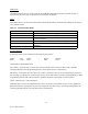
RSSI
The RSSI panel shows the current RSSI (received signal strength indicator) level (in dBm) while the local unit is
receiving.
Channel
The Channel field allows the user to select one of the 8 programmed channels for the unit’s use.
Rx/Tx Frequency
The Rx and Tx Frequency fields display the current receive and transmit frequencies.
F5
Pressing the F5 key causes the unit to transmit on the programmed transmit frequency.
F6
Pressing the F6 key causes the unit to go to receive on the programmed receive frequency.
F9
Pressing the F9 key causes the programmer to read the current settings from the module.