
User Manual

SECTION 2
INSTALLATION
2-1
Part No. 001-2100-101
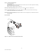
Figure 2-1 JSLM
2
Module
2.1 PRE-INSTALLATION CHECKS
Unpack the JSLM
2
Module. Inspect the unit to ensure the Module was not damaged during shipment. Save the
packing material and documentation.
2.2 INTERFACING WITH THE JSLM
2
2.2.1 PROGRAMMING AND POWER CABLE
Programming and pre-installation checks may be performed with the Programming Cable supplied in the JSLM
2
Field Programming Kit (Part Number 250-2100-001). For final installation, a Dataradio JSLM
2
Accessory /
Interconnect Power Cable is available (see Figure 2-2). See Appendix A for the Technical Support Application
note to interface the JSLM
2
with the external 1200 Baud Modem.
2.2.2 ANTENNA AND VSWR
A VSWR measurement of the antenna system should be made before the module is put into service. An accurate
VSWR meter or directional wattmeter appropriate for the frequency of operation should be used. A VSWR of less
than 2:1 is recommended. If the VSWR reading is high, check cables and connectors. Verify the antenna is
properly installed and is specified to operate on your frequency.
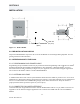
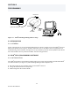
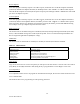
2.2.3 CONNECTOR J204 USER INTERFACE
Connector J204 (DA-15) provides the interface with the JSLM
2
module. This is a 15-pin, female connector. See
Appendix A for the Technical Support Application note to interface the JSLM
2
with the external 1200 Baud
Modem.
Antenna Connector
DA-15
(15 pin D)
(BNC)
Pin 9
Pin 1