
User Manual

1-5
Part No. 001-2100-101
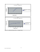
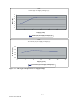
Output Power vs Supply Voltage See Figures 1-2, 1-3
RF Output Impedance 50 ohms
Modulation Distortion < 3% (Psophometrically weighted)
Spurious and Harmonic FM <
-20 dBm
FM Hum and Noise -40 dB, -35 dB (242-2110-710)
TRANSMIT AUDIO RESPONSE referenced to 1 kHz tone:
Auxiliary In w/o pre-emphasis +1/−3 dB from 300 Hz to 2.5 kHz
Auxiliary In with pre-emphasis +1/-3 dB with 6 dB pre-emphasis
Audio In +1/-3 dB with 6 dB pre-emphasis
M OD U L ATI O N C A PA B IL I TY @ 1 kH z t o ne : ( F a ct o ry Se t )
Auxiliary In w/o pre-emphasis 40 mVrms
± 20% for 60% of rated deviation
Auxiliary In with pre-emphasis 200 mVrms
± 20% for 60% of rated deviation
Audio In 30 mVrms
± 20% for 60% of rated deviation
TRANSMIT AUDIO DISTORTION
A u x i l i a r y I n < 3 % ( P s o p h o m e t r i c a l l y w e ig h t e d )
Audio In <3%(Psophometrically weighted)
TRANSMIT ATTACK TIME <15 ms from PTT to 100% rated power out
MODULATION CAPABILITY MIN/MAX ADJUSTMENT
Auxiliary In w/o pre-emphasis 10-80 mVrms (electronically programmable)
Auxiliary In with pre-emphasis 50-300 mVrms
Audio In No adjustment available
Measurements per TIA/EIA 603 or Dataradio COR Ltd. Specification 003-0000-000.
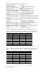
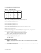
Table 1-2 VHF JSLM
2
RSSI Voltages vs RF Input Level @ J204, Pin 11
Table 1-3 UHF JSLM
2
RSSI Voltages vs RF Input Level @ J204, Pin 11
RF Input RSSI Typical RSSI Low RSSI High
Level Voltage Voltage Voltage
dBm 610 & 710 610 & 710 610 & 710
-120
0.69 0.40 0.98
-110
0.85 0.50 1.19
-100
1.02 0.66 1.38
-90
1.21 0.79 1.63
-80
1.38 0.99 1.77
-70
1.56 1.13 1.99
-60
1.75 1.32 2.18
-50
1.95 1.47 2.42
RF Input RSSI Typical RSSI Low RSSI High
Level Voltage Voltage Voltage
dBm 210 & 510 210 & 510 210 & 510
-120
0.85 0.42 1.28
-110
1.00 0.45 1.55
-100
1.19 0.57 1.81
-90
1.38 0.86 1.90
-80
1.55 0.95 2.15
-70
1.73 1.16 2.31
-60
1.93 1.25 2.60
-50
2.09 1.79 2.40