
User Manual

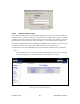
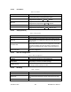
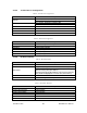
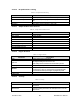
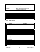
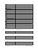
Table Of Contents
- Product Overview
- Installation
- Physical Description
- Operation & Configuration
- Local and Remote (OTA) Configuration
- Over-the-Air Firmware Upgrade
- Browser-Based Setup and Status
- LAN Setup
- Login Screen
- Interface
- Test & Save Parameters Buttons Behavior
- Unit Status
- Setup (General)
- Basic IP Configuration
- RF Setup
- Terminal Server Configuration
- Advanced IP Configuration
- RF Network Setup
- Broadcast / Multicast
- IP Optimization & Tuning
- Simple Network Time Protocol
- Hopper Network
- Security
- Network Statistics
- Packet Statistics
- Event Log
- RF Test
- FTP Transfer
- RSSI Table
- Manuals & Support
- Troubleshooting & Testing
- Specifications

4.3.3.2 Unit Status
Table 4 - Unit Status
Command Description
Banner
Displays HiPR-900 information retrieved from the connected unit. Have
this information handy if contacting Dataradio support.
Station Name
Displays name of connected unit.
Configured under Setup Basic Î General Î StationID
Time Zone
Displays local time zone.
Configured under Setup Advanced Î SNTPÎ TimeZone
Local Time Displays local time computed using UTC time and Time Zone
Zulu Time
Displays UTC time.
Configured under Setup Advanced Î SNTPÎ SNTP UTC Time
4.3.3.3 Setup (General)
Table 5 - Setup (General)
Command Description
Station Name Station name identifier – Enter string up to forty characters in length
System ID
Factory default ID is zero. Dataradio recommends changing it to some
other value unique to each HiPR-900 network to prevent collision and
security reason.
Connection mode
Remote/Master
Within a HiPR network, one unit has to be configured as a master that
the remotes synchronize to. It can be any unit in a system but is nor-
mally the one considered the base unit for coverage and support rea-
sons.
IP Forwarding mode
Bridge / Router modes – Defaults to Bridge mode. Use Router for more
advanced IP configurations.
4.3.3.4 Basic IP Configuration
Table 6 - Basic IP Configuration
Command Description
IP Address Set to valid unique IP address for each individual unit
Network Mask
Set to valid IP netmask for each individual unit (may be same or differ-
ent depending on customer’s IP network topology).
IP Default Gateway
Set to valid Default Gateway.
May change for different groups or locations
4.3.3.5 RF Setup
Table 7 - RF Setup
Command Description
Power Level Sets power level between 0.1 and 1.0 watt (Default 1.0)
Airlink speed
256000, 512000 (Default) - Sets the maximum speed the HiPR900 will
use for data packet transmissions. Slower speed preferred for longer
range.
SubBand Mask Indicates which channels are to be used in the shared band.
120 40515-100a HiPR900 User Manual
24