
User Manual
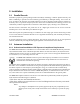
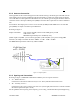
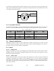
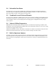
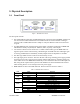
Table Of Contents
- Product Overview
- Installation
- Physical Description
- Operation & Configuration
- Local and Remote (OTA) Configuration
- Over-the-Air Firmware Upgrade
- Browser-Based Setup and Status
- LAN Setup
- Login Screen
- Interface
- Test & Save Parameters Buttons Behavior
- Unit Status
- Setup (General)
- Basic IP Configuration
- RF Setup
- Terminal Server Configuration
- Advanced IP Configuration
- RF Network Setup
- Broadcast / Multicast
- IP Optimization & Tuning
- Simple Network Time Protocol
- Hopper Network
- Security
- Network Statistics
- Packet Statistics
- Event Log
- RF Test
- FTP Transfer
- RSSI Table
- Manuals & Support
- Troubleshooting & Testing
- Specifications

3. Physical Description
3.1 Front Panel
PWR
SYNC
LNK
ACT
+ -
RX / TX
RX
TX/RX
DATA
SETUP
POE
LAN
Figure 7 - HiPR-900 Front Panel
The front panel includes:
• One standard RJ-45 autosensing 10/100 UTP Ethernet connection with Auto-MDIX. Supports di-
rect connection to both Terminal Devices and Ethernet hubs or switches without resorting to
crossover cables. LED indicators make it simple to verify that Ethernet cables and connections
are good.
• Two DE-9F RS232 ports. Serial baud rates from 1200 to 115,200 are supported. The HiPR-900
radiomodem is factory set (default) for 19200 b/s, 8 bits, no parity, and 1 stop bit.
• The antenna connector for the transceiver is a female 50-ohm TNC type. The HiPR-900 is de-
signed to operate with an antenna having a maximum gain of 10 dBi. Antennae with higher gain
are strictly prohibited (FCC and Industry Canada). Required antenna impedance is 50 ohms.
• One TNC-type female antenna connector for the auxiliary receiver
• One right-angle power connector. The 10 to 30 VDC wide-range switching power supply permits
powering from 12 volt as well as 24 volt systems, and the high-efficiency switching design runs
cooler with less loss. The HiPR-900 automatically senses and switches between its DC input and
PoE, using the DC input if both are present. This minimizes the load on PoE Ethernet switches
while allowing them to act as a backup to the local power supply.
• HiPR-900 has five dual-color LED indicators. Their functions are shown in Table 3.
Table 3 - HiPR-900 LEDs indications
LED Color Definition
ACT Green Data transmission or reception activity
Green Connection OK
LINK
Amber Collision
Green Data reception activity
Amber Data transmission activity
Tx / Rx
Red Receive CRC error
Remote: In sync with Master
Green
Master: Normal
Remote: Loss of Master sync
SYNC
Red
Master: Failure
Green Normal
Amber (at boot-up) Normal (approx 5 secs)
Amber Application failure
PWR
Red Hardware failure
120 40515-100a HiPR900 User Manual
19