
User Manual
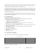
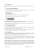
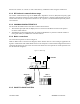
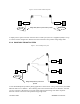
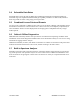
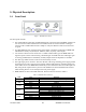
Table Of Contents
- Product Overview
- Installation
- Physical Description
- Operation & Configuration
- Local and Remote (OTA) Configuration
- Over-the-Air Firmware Upgrade
- Browser-Based Setup and Status
- LAN Setup
- Login Screen
- Interface
- Test & Save Parameters Buttons Behavior
- Unit Status
- Setup (General)
- Basic IP Configuration
- RF Setup
- Terminal Server Configuration
- Advanced IP Configuration
- RF Network Setup
- Broadcast / Multicast
- IP Optimization & Tuning
- Simple Network Time Protocol
- Hopper Network
- Security
- Network Statistics
- Packet Statistics
- Event Log
- RF Test
- FTP Transfer
- RSSI Table
- Manuals & Support
- Troubleshooting & Testing
- Specifications

Figure 5 - Point-to-Point IP Network System
HiPR-900
HiPR-900
DTE
DTE
Bridge Mode (Ethernet) connections possible
Network
Network
A simple point-to-point connection is shown above. In this system, the user's equipment (DTE) is set up
in a master-remote configuration. Ethernet network connection is also possible using bridge mode.
2.3.6 POINT-MULTIPOINT SYSTEM
Figure 6 - Point-to-Multipoint System
HiPR-900
HiPR-900
Remote
Remote
Remote
HiPR-900
HiPR-900
Master
Network
Bridge Mode (Ethernet) connections
possible
A basic Point-Multipoint system for polling application is shown above. Using a web browser, one HiPR-
900 unit must be set to “Master”. The remaining units in the network must be set to “Remote”. All units
are set to “selective” data delivery to prevent remote stations from hearing each other's responses.
Ethernet network connection is also possible using bridge mode.
120 40515-100a HiPR900 User Manual
17