Dataradio Sentry 4G 900TM 900 MHZ 802.16-2005 SUBSCRIBER STATION BROADBAND ROUTER User Manual P/N 001-9193-001 Version 1 July 2009 PRE LI MINARY AERCEPT DATARADIO L ANDCELL OMEGA SMARTLINK 299 Johnson Avenue, Suite 110 | Waseca, MN 56093 | t 507.833.8819 | f 507.833.6748 | calamp.
TABLE OF CONTENTS 1. PREFACE .......................................................................................................................................................................... 4 1.1 COPYRIGHT NOTICE ................................................................................................................................................................ 4 1.2 ROUTER USE ..............................................................................................................
TABLE OF CONTENTS FIGURE 5 - LOCAL AREA CONNECTION PROPERTIES (WINDOWS XP) ......................................................................................................... 15 FIGURE 6 - INTERNET PROTOCOL (TCP/IP PROPERTIES) ......................................................................................................................... 16 FIGURE 7 - SENTRY 4G ROUTER HOMEPAGE ....................................................................................................................
PREFACE 1. PREFACE 1.1 Copyright Notice ©2009 CalAmp Corp. All Rights Reserved. This manual covers the operation of the CalAmp/ Dataradio Sentry 4G 900 TM router. Specifications described are typical only and are subject to normal manufacturing and service tolerances. CalAmp reserves the right to modify the equipment, its specifications or this manual without prior notice, in the interest of improving performance, reliability, or servicing.
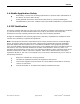
PREFACE 1.4 Mobile Application Safety Road safety is crucial. Do not change parameters or perform other maintenance of the Sentry 4G router while driving. Avoid potential interference with vehicle electronics by correctly installing the Dataradio Sentry 4G router. CalAmp Corp recommends installation by a professional. 1.5 FCC Notification This device complies with part 15 of the FCC rules.
PRODUCT OVERVIEW 2. PRODUCT OVERVIEW 2.1 General Description The Dataradio Sentry 4G 900TM from CalAmp provides high-speed, long-range 802.16-2005 compliant connectivity in the license-free 900 MHz band. Based on industrial grade IEEE 802.16-2005 technology, it features extensive routing capabilities with an easy-to-use interface and comprehensive remote management. Built-in GPS, two Ethernet ports and an optional 802.11b/g access point allows connectivity in the office or on the road.
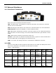
PRODUCT OVERVIEW 2.3 External Interfaces 2.3.1 Front Panel Connections Figure 1 - Dataradio Sentry 4G Router Front Panel Sentry 4G router front panel connections include: TRX: Two TNC female, Transmit/Receive antenna connections. See section 2.6 “Antenna options” for more information. WiFi: RP-SMA jack, WiFi antenna. See section 2.6 “Antenna options” for more information. ETH0 and ETH1: Inputs for standard or crossover Ethernet cable GPS: SMA female, GPS antenna connector. This input requires a 3.
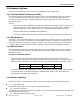
PRODUCT OVERVIEW Point) ETH0 No link ETH1 No activity 100mbps link N/A Activity RX/TX Activity RX/TX Activity 10 mbps link N/A N/A N/A N/A N/A N/A N/A 2.4 RJ-45 Ethernet Port Integration Parameters Table 2 below provides the information to purchase Ethernet cables to integrate the Sentry 4G product into your system. Note: The Sentry 4G unit can accept either a standard or cross over Ethernet cable.
PRODUCT OVERVIEW Figure 2 - Dataradio Sentry 4G Power Cable Connections Table 3 - Power supply connections Pin 1 2 3 4 Color Thin Red Red Blue Yellow Description Ignition Sense DC Power, 10 to 30V DC Ground Officer down alarm If connection to an AC supply is desired, an AC/12VDC power supply and cable are available.
PRODUCT OVERVIEW 2.6 Antenna Options Antennas are available for Sentry 4G routers installations from CalAmp Corp. 2.6.1 Transmit/Receive Antennas (TRX) The primary antenna connections on the Sentry 4G unit are TNC female connectors; therefore you must purchase antennas with TNC male connectors. Do not select TNC antennas with “reverse polarity” or RP-Male. Mounting options and cable lengths are the user’s choice and application specific.
PRODUCT OVERVIEW Constraints are TX spacing of at least 60cm/23.62 inch from all transmitting antennas and a clear view of the sky. “W” – WiFi antenna Constraints are TX spacing of at least 8 inches or 20 cm from all transmitting antennas Note: For units utilizing diversity antennas, best overall operation is achieved utilizing antennas with equal gains WARNING: As per FCC rules, all Sentry 4G transmitting antennas should be at a minimum of eight (8) inches (approximately 20 centimeters) from all persons.
NETWORKING BASICS 3. Networking basics 3.1 General Networking Definitions The Sentry 4G router is based on Ethernet connectivity and follows general IP networking guidelines and terminology. Below are definitions of some basic network terminology as they pertain to the Sentry 4G environment.
NETWORKING BASICS PPP Private IP address RIP SOFDMA SSID Subnet Subnet Mask TKIP/AES WAN WEP WiFi (802.11b, 802.11g) WiFi Access Point (802.11) WiFi Client (802.11 Infrastructure mode) WLAN WPA/WPA2 001-9193-001 Version 1 process. Ports are typically used to map data to a particular process running on a computer. Point-to-point Protocol: creating a direct link between two nodes in network communication. Private IP addresses are addresses that will not be routed on external networks.
GETTING STARTED 4. GETTING STARTED 4.1 Package Contents Sentry 4G router Quick Start Guide Power cable User Manual and Quick Start Guide on CD Mounting Screws 4.2 Setup Requirements Sentry 4G router Computer running any operating system with a web browser installed such as Microsoft Internet Explorer version 6.0 or later or Firefox version 2.0 or later.
GETTING STARTED 4.4 Configuring Local PC 1. Verify network settings on local PC are set to automatically detect IP and DNS server. The path to network settings varies with the version of Windows you are using. Windows XP: Start-> Control Panel -> Network Connections Windows 2000: Start -> Settings -> Network and dial up connections 2. Select the appropriate network connection, typically the Local Area Connection -> right click on the connection and select “Properties” 3.
GETTING STARTED Figure 6 - Internet Protocol (TCP/IP Properties) 4.5 Sentry 4G Router Setup 1. Power on the Sentry 4G router with 10-30VDC power supply. 2. In an Internet browser, enter http://192.168.1.50. This will bring up the Sentry 4G product login page (Note: It may take 30 seconds from initial power-up for the homepage to be available.) 3. Login to the device Default Login values User logon: admin password: password 4. This brings up the Sentry 4G product homepage.
GETTING STARTED Figure 7 - Sentry 4G Router Homepage 001-9193-001 Version 1 Page 17 of 48 Sentry 4G 900TM User Manual
CONFIGURATION 5. Sentry 4G Configuration This section explains status information and configuration options available on all HTML pages. 5.1 General Instructions The following instructions are common to all HTML pages The Help, Home and Reset links are located at the top right of all HTML pages. Help: Select this link on any of the devices configuration pages to bring up the help text for that screen. Home: Select this link to return to the home page of the router.
CONFIGURATION Figure 8 - Sentry 4G Router Unit Status 001-9193-001 Version 1 Page 19 of 48 Sentry 4G 900TM User Manual
CONFIGURATION 5.2.1 Home Page Parameter Descriptions System Information Unit ID: Sentry4G unit identification number (configured under General Settings). System Up Time: System Up Time displays a counter that starts when the unit is powered on and resets when the unit is powered down or hardware reset. Software Version: This reflects the version of application software loaded on the unit. WWAN Interface Status: indicates if the device has an established connection to the WWAN.
CONFIGURATION Figure 9 - Sentry 4G Router WWAN Main 5.3.2 Status The Status tab of the WWAN page displays the current WWAN interface status including firmware version, link status, and link information. Information on this page is read-only. Figure 10 - Sentry 4G Router WWAN Status 5.3.3 Settings The Sentry4G router uses EAP-TTLS (Extensible Authentication Protocol-Tunneled Transport Layer Security) to obtain authorization and traffic key material from the BTS. The EAP-TTLS is disabled by default.
CONFIGURATION Figure 11 - Sentry 4G Router WWAN Settings 001-9193-001 Version 1 Page 22 of 48 Sentry 4G 900TM User Manual
CONFIGURATION Once EAP-TTLS authentication is enabled, the IP configuration for the WWAN interface will be obtained through the BTS. Note: The IP address for the WWAN interface is displayed under the Unit Status If no authentication is selected, the IP address for the WWAN interface must be entered manually. 5.3.3.1 DNS Configuration DNS servers can be configured as follows: Mode: Dynamic (Default): Obtain DNS IP addresses dynamically from a DHCP server.
CONFIGURATION 5.4 LAN Settings (ETH0 and ETH1) Figure 12 - IP Settings Sentry4G router features two Ethernet ports. The ETH0 and ETH1 Settings pages contain the basic configuration information required to customize your LAN with the Sentry 4G router as the network connection point. User configuration will primarily occur on this page. 5.4.1 IP Settings 5.4.1.1 IP Configuration Ethernet IP address: LAN IP of the SENTRY 4G unit.
CONFIGURATION DNS Auto: The command enables/disables the Sentry 4G DNS server. Except in special cases, this should always be enabled. 5.4.1.3 DHCP Server Configuration DHCP Server: (Dynamic Host Configuration Protocol) A protocol used by client devices that are connected to the LAN port of this device to automatically obtain an IP address assigned by this server/router.
CONFIGURATION When these settings are complete, the PC will have network access. 5.4.1.5 Static IP Setup If your network requires each PC to have a statically set LAN IP addresses, follow the previous procedure for all PCs on the network. If the network requires a mix of static and dynamically assigned IP addresses, assign static IPs outside the DHCP address range for PCs that require static IP addresses and allow the Sentry 4G router DHCP to assign the remaining PC IP addresses. 5.4.
CONFIGURATION 5.5.1 WiFi (WLAN)Main WiFi settings provide user configuration for optimal WiFi interface operation.
CONFIGURATION 5.5.2 WiFi (WLAN)Wireless Settings (Client) The user can configure up to 20 access points. Note: All access points must run a DHCP server. In wireless client mode, the Sentry 4G unit will try to connect to the Access Point with the strongest signal on the list. When the Sentry 4G unit connects to an access point, it starts a DHCP client service. The DHCP server running on the access point must provide an IP address, netmask, and gateway to the Sentry 4G unit.
CONFIGURATION Note: For a 64-bit key, keys are 5 character strings long if WEP Key Type is set to ASCII and 10 hexadecimal digits long if WEP Key Type is set to HEX. For a 128-bit key, keys are 13 character strings long if WEP Key Type is set to ASCII and 26 hexadecimal digits long if WEP Key Type is set to HEX. The following table shows examples of encryption keys depending on encryption type chosen.
CONFIGURATION 5.5.
CONFIGURATION DHCP Server DHCP Server: Enables or disables DHCP server on the WiFi interface Start IP Address: Starting IP address (defines the pool of addresses allocated for DHCP purpose) End IP Address: Ending IP address (defines the pool of addresses allocated for DHCP purpose) Lease Time: The period over which the IP address allocated to a DHCP client is referred to as a “lease”. Lease duration is the amount entered in seconds.
CONFIGURATION 5.5.5 WiFi (WLAN)Statistics Figure 17 - WiFi (WLAN) Statistics Transmit TX Packets: Number of packets sent by the Sentry 4G unit over the WiFi interface TX Bytes: Number of bytes sent by the Sentry 4G unit over the WiFi interface Receive RX Packets: Number of packets received by the Sentry 4G unit over the WiFi interface RX Bytes: Number of bytes received by the Sentry 4G unit over the WiFi interface 5.5.
CONFIGURATION 5.6 Router Settings Router settings provide advanced user configuration for large network setups. 5.6.1 Static Routes Figure 19 - Static Routes The Sentry 4G unit will automatically set up routing to all devices on the same subnet. In some cases however, the Sentry 4G unit may need to communicate with a previously existing subnet other than its own. This route cannot be automatically generated; it must be manually entered as a static route by the user.
CONFIGURATION Metric: This sets the priority of the routes compared to other static routed defined. The lower the number, the higher priority the route. Click on “Add” when all necessary information has been entered. The route will be shown on the bottom of the screen (under Static Routing Table). Additional routes can be added provided they have a unique Route no, name and metric. Routes can be deleted by clicking the Delete Entry option of the desired entry.
CONFIGURATION Figure 20 - IP Filtering 001-9193-001 Version 1 Page 35 of 48 Sentry 4G 900TM User Manual
CONFIGURATION 5.6.3 Port Forwarding Port Forwarding is used to provide remote access to third party devices on the LAN, such as Web Cameras or printers. Port Forwarding routes incoming requests from the WWAN, with a specific port to a local device with a static IP. Figure 21 - Port Forwarding 5.6.4 Routing Table The table in Figure 22 shows a list of all routes (static and dynamic). Figure 22 - Routing Table 5.6.
CONFIGURATION Figure 23 - Interface Priority 5.7 General Settings 5.7.1 General Settings-Unit ID The Sentry4G unit identification number is configured under General SettingsUnit ID. 5.7.2 Advanced Settings-Password The Sentry 4G unit’s web interface management login details are modified using the Password tab of the Advanced Settings page. To change the login details, enter the current and new password. The new password must be entered twice (reconfirmed). 5.7.
CONFIGURATION The following should be entered into a browser on a remote PC to remote login to the Sentry 4G router. The Sentry 4G unit must have remote administration enabled for this functionality to work. Note: “HTTP” must be specified or browser will assume other uses http://70.209.115.93:8080 “WWAN IP Address" On Unit Status page "Configuration Port" on "Remote Administation" page. Figure 25 - Example of Remote Login 5.7.
CONFIGURATION Typical sensitivity -135 dBm Reacquisition time Less than 2 seconds Average Cold/Warm/Hot Start time to first fix Under 45/15/3.5 seconds Position Accuracy GPS Standard Positioning Service (SPS) <15 meters DGPS (WAAS) corrected <3 meters The GPS page allows the user to see the GPS status and configure remote or local delivery of GPS position reports. Viewing the GPS data from a local or remote PC requires a UDP port listener program be installed on the PC.
CONFIGURATION 5.8.2 AAVL Settings (Local and Remote Delivery) Figure 28 - AAVL Settings TAIP Vehicle ID: User assigned number to identify the vehicle or Sentry 4G unit that each GPS report belongs to. This will be reported in the GPS messages if TAIP with ID is selected for TCP Server Format and/or UDP Host format. Configured under Basic Settings.
CONFIGURATION 5.8.3 Local Delivery The GPS data can be delivered to up to two local PCs with UDP viewer programs can provide data through a TCP connection, e.g. telnet. GPS data will be delivered once per second to all local PCs TCP Server Format: Select one of the following options for the format of the GPS messages TAIP no ID: Trimble ASCII Interface Protocol, a Trimble specified digital communication interface. When this option is selected, the TAIP vehicle ID is not included in the GPS messages.
CONFIGURATION 5.9 I/O Settings The Sentry 4G router supports the following I/Os: Ignition Sense One external digital alarm See Table 5 for pinout. J4 Pin 1 4 Signal I/O Ignition Sense Input to Sentry4G External Alarm Input to Sentry4G Description / specification Standard ignition-on signal 1. Pin 1 is the left most pin when looking directly at the front panel. Maximum voltage above which Ignition Sense will be detected as ignition asserted = 9.
CONFIGURATION 5.9.1 I/O Configuration The Sentry 4G I/O subsystem is configured via the Sentry 4G WEB pages. Status Monitoring is provided via NMEA-based protocol. The Sentry 4G I/O subsystem operates according to a manager/agent model. The PC-hosted manager sends requests to the Sentry 4G I/O agent, which performs the required actions. The Sentry 4G agent reports alarms and indications to the PC-hosted manager.
CONFIGURATION Remember to save your settings for each configuration. Figure 30 - I/O Settings Figure 31 - I/O Settings-Labels .
CONFIGURATION 5.10 System Upgrade (Optional Service) It is possible to update the system by receiving an update file from CalAmp Corp. This may be done periodically to add features or fix errata. When you receive an update file, perform the following to update the unit. Upgrading can only be performed from a local PC, not remotely. Save the file on a local drive or network accessible directory. On the System Upgrade page (see Figure 32), browse to the update file and select it. Click Save.
SPECIFICATIONS 6. SPECIFICATIONS Product specifications are subject to change without notice. GENERAL SPECIFICATIONS Interface Connectors: Two 10/100 BaseT auto-MDIX, RJ-45 USB A Female Client port2 3-wire serial in a USB mini B female form factor Power Connector: 4-pin Weidmuller 1615550000 LED Indicators: PWR, STAT, GPS, 4G, WiFi, ETH0, ETH1 Antenna Interface: Two 4G Antennas: 50-Ohm TNC Female GPS Antenna: 50-Ohm, 3.3V SMA Female Two WiFi Antennas: 50-Ohm RP-SMA Plug Size: 7 (L) x 7 (W) x 2.
ABBREVIATIONS 7.
SERVICE AND SUPPORT 8. SERVICE AND SUPPORT 8.1 PRODUCT WARRANTY, RMA AND CONTACT INFORMATION CalAmp Corp guarantees that every Dataradio Sentry 4G router will be free from physical defects in material and workmanship for one (1) year from the date of purchase when used within the limits set forth in the Specifications section of this manual. Extended warranty plans are available.