Preliminary Dataradio Vanguard 3GTM (GSM Version) Rugged Cellular Radio Modem User Manual P/N 001-7001-100 Version 1 April 2009 AERCEPT DATARADIO LANDCELL OMEGA SMARTLINK 299 Johnson Avenue, Suite 110 | Waseca, MN 56093 | t 507.833.8819 | f 507.833.6748 | calamp.
Preliminary TABLE OF CONTENTS 1. PREFACE ...................................................................................................................................................................... 4 1.1 COPYRIGHT NOTICE ................................................................................................................................................................ 4 1.2 MODEM USE.......................................................................................................
Preliminary TABLE OF CONTENTS FIGURE 1 ‐ DATARADIO VANGUARD 3G RADIO MODEM’S FRONT PANEL ..................................................................................................... 8 FIGURE 2 ‐ DATARADIO VANGUARD 3G RADIO MODEM’S BACK PANEL ....................................................................................................... 9 FIGURE 3 ‐ DATARADIO VANGUARD 3G POWER CABLE CONNECTIONS.................................................................................................
Preliminary PREFACE 1. PREFACE 1.1 Copyright Notice ©2009 CalAmp Corp. All Rights Reserved. This manual covers the operation of the CalAmp Dataradio Vanguard 3G CDMA Cellular Modem. Specifications described are typical only and are subject to normal manufacturing and service tolerances. CalAmp reserves the right to modify the equipment, its specifications or this manual without prior notice, in the interest of improving performance, reliability, or servicing.
Preliminary • PREFACE Operation in the presence of other electronic equipment may cause interference if equipment is incorrectly protected. Follow recommendations for installation from equipment manufacturers. 1.4 Mobile Application Safety • Do not change parameters or perform other maintenance of the Vanguard 3G modem while driving. • Road safety is crucial. Observe National Regulations for cellular telephones and devices in vehicles.
Preliminary PRODUCT OVERVIEW 2. PRODUCT OVERVIEW 2.1 Device Identification 2.1.1 Label Information The label contains the CalAmp part number, serial number, MAC ID, FCC ID and the IMEI numbers in both Hex and decimal format. 2.2 General Description The Dataradio Vanguard 3G Modem from CalAmp Corp is the ideal solution for a wide range of Internet Access, Corporate Network and wireless IP connectivity requirements.
Preliminary PRODUCT OVERVIEW 2.
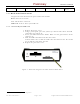
Preliminary PRODUCT OVERVIEW 2.5 External Interfaces 2.5.1 Front Panel Connections Figure 1 - Dataradio Vanguard 3G radio modem’s Front Panel Vanguard 3G radio modem front panel connections include: GPS: SMA female, GPS antenna connector. This input requires a 3.3V, GPS antenna with an SMA connection. For best coverage, use an active GPS antenna with a gain of >25dBm. PWR: 9-28 VDC; the mating connector is a Molex 43025-0400 4 position connector. LAN: Input for standard or crossover Ethernet cable.
Preliminary Acquired in View PRODUCT OVERVIEW Detected Satellites, no fix yet 2.5.3 Back Panel Connections Vanguard 3G radio modem back panel connections include: Reset: Hard reset button2 I/O: I/O interface connector SIM Card: A slot to insert your SIM card 2.5.3.1 To install your SIM card: 1. Remove Protective cover 2. Using a pencil point, press the yellow eject button and remove the SIM card holder (see Figure 2) 3. Insert your SIM card into the holder.
Preliminary PRODUCT OVERVIEW 2.6 RJ-45 Ethernet Port Integration Parameters Table 2 below provides the information to purchase Ethernet cables to integrate the Vanguard 3G product into your system. Note: The Vanguard 3G radio modem can accept either a standard or cross over Ethernet cable. Table 2 - Standard RJ-45 Ethernet Pin-out Pin 1 2 3 4 5 6 7 8 Function TX + TX RX + RX - Color White/Orange Orange/White White/Green Blue/White White/Blue Green/White White/Brown Brown/White 2.
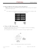
Preliminary PRODUCT OVERVIEW Table 3 - Power supply connections Pin 1 2 3 4 Color Red Blue White NA Description DC Power, 9 to 28V DC Ground Ignition Sense No Connect Figure 4 - Dataradio Vanguard 3G Power Cable Connections Red Blue White - GND + Out Ignition Sense Delay Timer In Figure 5 -Alternative Dataradio Vanguard 3G Power Cable Connections with Ignition Sense Delay Timer If connection to an AC supply is desired, an AC/12VDC power supply and cable are available.
Preliminary PRODUCT OVERVIEW 2.8 Antenna Options Antennas are available for Vanguard 3G radio modems installations from CalAmp Corp. 2.8.1 Primary Cellular Antenna The Vanguard 3G product requires a multi-band cellular antenna for operation in the 800 MHz band, the 1900 MHz band, and the 2100 MHz band. The primary antenna connection on the Vanguard 3G unit is a TNC female connector; therefore you must purchase an antenna with a TNC male connector.
Preliminary PRODUCT OVERVIEW To reduce potential radio interference to other users, the antenna type and its gain should be so chosen that the equivalent isotropically radiated power (e.i.r.p.) is not more than that permitted for successful communication. 2.8.
Preliminary PRODUCT OVERVIEW For installation of ground-plane dependent antennas (main cellular and WiFi antennas), the center of the metal surface used for mounting is preferable for best omni-directional pattern. For groundplane independent antennas (diversity and GPS antennas), installation may be close to the edges of the surface. For vehicular installations CalAmp recommends the following antenna positions: Most preferred for all antennas: centerline of roof.
Preliminary NETWORKING BASICS 3. Networking basics 3.1 General Networking Definitions The Vanguard 3G cellular modem is based on Ethernet connectivity and follows general IP networking guidelines and terminology. Below are definitions of some basic network terminology as they pertain to the Vanguard 3G environment.
Preliminary TKIP/AES WAN WEP WiFi (802.11b, 802.11g) WiFi Access Point (802.11 Ad-Hoc mode) WiFi Client (802.11 Infrastructure mode) WLAN WPA/WPA2 001-7001-100 Version 1 Version NETWORKING BASICS “Temporal Key Integrity Protocol” is an encryption method used by the WiFi interface when operating in WPA mode. TKIP was designed to solve security issues in WEP (it is considered stronger then WEP).
Preliminary GETTING STARTED 4. GETTING STARTED 4.1 Package Contents Vanguard 3G cellular modem Quick Start Guide Power cable and Fuse User Manual and Quick Start Guide on CD Mounting Bracket and Screws 4.
Preliminary GETTING STARTED 4.4 Configuring Local PC 1. Verify network settings on local PC are set to automatically detect IP and DNS server. The path to network settings varies with the version of Windows you are using. Windows XP: Start-> Control Panel -> Network Connections Windows 2000: Start -> Settings -> Network and dial up connections 2. Select the appropriate network connection, typically the Local Area Connection -> right click on the connection and select “Properties” 3.
Preliminary GETTING STARTED Figure 9 - Internet Protocol (TCP/IP Properties) 4.5 Vanguard 3G Radio Modem Setup 1. Power on the Vanguard 3G radio modem with 9-28VDC 15-Watt supply. 2. In an Internet browser, enter http://192.168.1.50. This will bring up the Vanguard 3G product login page (Note: It may take 30 seconds from initial power-up for the homepage to be available.) 3. Login to the device Default Login values User logon: admin password: password 4. This brings up the Vanguard 3G product homepage.
Preliminary GETTING STARTED Figure 10 - Vanguard 3G radio modem Homepage 001-7001-100 Version 1 Version Page 20 of 65 Vanguard 3G User Manual GSM
Preliminary GETTING STARTED 4.6 Provisioning the Vanguard 3G Radio Modem IMPORTANT NOTE: The Vanguard 3G cellular radio modem requires an active cellular data service contract and a SIM card for provisioning. Verify that your cellular service contract is a data service contract with packet data NOT circuit switched technology. If you do not have an active data contract or a SIM card, contact your service provider. Note: The Vanguard 3G radio modems are carrier specific.
Preliminary GETTING STARTED 5. Select “Activation Tab” (Figure 12). Check status under “SIM operation”. If “No_operation_required” is displayed, proceed to next step. If “Enter_CHV1” is displayed, a PIN code is required for operation. Enter your PIN code in the designated space and click “Save”. Figure 12 - Vanguard 3G product Cellular (WAN) page Activation 6. Once the unit is activated, browse to an Internet web page to confirm connectivity.
CONFIGURATION Preliminary Vanguard 3G 5. Vanguard 3G Configuration This section explains status information and configuration options available on all HTML pages. 5.1 General Instructions The following instructions are common to all HTML pages The Help, Home and Reset links are located at the top right of all HTML pages. Help: Select this link on any of the devices configuration pages to bring up the help text for that screen. Home: Select this link to return to the home page of the modem.
CONFIGURATION Preliminary Vanguard 3G Figure 13 - Vanguard 3G Radio Modem Home Page 001-7001-100 Version 1 Version Page 24 of 65 Vanguard 3G User Manual GSM
CONFIGURATION Preliminary Vanguard 3G 5.2.1 Home Page Parameter Descriptions System Information Unit ID: Unit identification number (configured under Basic Settings). System Up Time: System Up Time displays a counter that starts when the unit is powered on and resets when the unit is powered down or hardware reset. Note: This counter does NOT indicate how long the WAN connection has been up. Software Version: This reflects the version of application software loaded on the unit.
CONFIGURATION Preliminary Vanguard 3G Subnet Mask: This subnet mask is assigned by the carrier and is not configurable by the user. P-t-P: WAN IP address of the network access point of the cellular carrier GSM Connection Service Type: Service Type indicates the type of service connection. Service Mode: UMTS/HSDPA, UMTS/HSPA, or EDGE/GPRS Carrier: Registered Carrier Roaming Status: Roaming Status indicates the unit roaming status. Status is ROAMING or NOT ROAMING.
Preliminary CONFIGURATION Vanguard 3G Figure 14 - Vanguard 3G Radio Modem Cellular (WAN) Status Page 5.3.2 Activation SIM configuration parameters (refer to Figure 12) To change PIN Code: 1. Enter your old code under “Old Pin Code” 2. Enter your new code under “Pin code (CHV1) 3. Click Save Pin unblock code: The code required to unlock a GSM SIM card that was disabled after an incorrect PIN code was entered three times in a row.
CONFIGURATION 001-7001-100 Version 1 Version Preliminary Page 28 of 65 Vanguard 3G Vanguard 3G User Manual GSM
CONFIGURATION Preliminary Vanguard 3G 5.4 LAN Settings Figure 15 - LAN Settings Page The LAN Settings page contains the basic configuration information required to customize your LAN with the Vanguard 3G radio modem as the network connection point. User configuration will primarily occur on this page. PPPoE settings can be found under “Advanced” tab (see section 5.4.2). 5.4.1 IP Settings 5.4.1.1 IP Configuration Ethernet IP address: LAN IP of the VANGUARD 3G radio modem.
CONFIGURATION Preliminary Vanguard 3G 5.4.1.2 DNS Masquerade See the definition for DNS in Network Basics in section 3.1 above. DNS Auto: The command enables/disables the Vanguard 3G DNS server. Except in special cases, this should always be enabled. One exception to this is if using a PPPoE connection. 5.4.1.
CONFIGURATION Preliminary Vanguard 3G – IP address: Set a unique address on the same subnet as the Vanguard 3G radio modem – Subnet Mask: Set to the same value as the CiPHRs Ethernet Subnet Mask field – Default Gateway: Ethernet IP of the Vanguard 3G radio modem – Preferred DNS: Ethernet IP of Vanguard 3G radio modem When these settings are complete, the PC will have network access. 5.4.1.
CONFIGURATION Preliminary Vanguard 3G Figure 16 - MAC Pairing 5.5 WiFi (WLAN) A Vanguard 3G unit can operate in an access point mode (Ad-Hoc) and in a client mode. In access point mode, the Vanguard 3G radio modem offers wireless tether. It forwards local WiFi traffic to application servers over the cellular network and works in parallel with Ethernet connection, providing for simultaneous WiFi and Ethernet connections (see Figure 17A).
CONFIGURATION Preliminary Vanguard 3G 5.5.1 WiFi (WLAN)ÆMain WiFi settings provide user configuration for optimal WiFi interface operation.
Preliminary CONFIGURATION Vanguard 3G 5.5.2 WiFi (WLAN)ÆWireless Settings (Client) The user can configure up to 20 access points. Note: All access points must run a DHCP server. In wireless client mode, the Vanguard 3G unit will try to connect to the Access Point with the strongest signal on the list. When the Vanguard 3G unit connects to an access point, it starts a DHCP client service. The DHCP server running on the access point must provide an IP address, netmask, and gateway to the Vanguard 3G unit.
CONFIGURATION Preliminary Vanguard 3G For a 128-bit key, keys are 13 character strings long if WEP Key Type is set to ASCII and 26 hexadecimal digits long if WEP Key Type is set to HEX. The following table shows examples of encryption keys depending on encryption type chosen.
Preliminary CONFIGURATION Vanguard 3G 5.5.
CONFIGURATION Preliminary Vanguard 3G DHCP Server DHCP Server: Enables or disables DHCP server on the WiFi interface Start IP Address: Starting IP address (defines the pool of addresses allocated for DHCP purpose) End IP Address: Ending IP address (defines the pool of addresses allocated for DHCP purpose) Lease Time: The period over which the IP address allocated to a DHCP client is referred to as a “lease”. Lease duration is the amount entered in seconds.
Preliminary CONFIGURATION Vanguard 3G 5.5.5 WiFi (WLAN)ÆStatistics Figure 21 - WiFi (WLAN)Æ Wireless Settings (Statistics) Transmit TX Packets: Number of packets sent by the Vanguard 3G unit over the WiFi interface TX Bytes: Number of bytes sent by the Vanguard 3G unit over the WiFi interface Receive RX Packets: Number of packets received by the Vanguard 3G unit over the WiFi interface RX Bytes: Number of bytes received by the Vanguard 3G unit over the WiFi interface 5.5.
CONFIGURATION Preliminary Vanguard 3G 5.6 Router Settings Router settings provide advanced user configuration for large network setups. 5.6.1 RIP Settings Not supported in the current version 5.6.2 Static Routes Figure 23 - Static Routes Screen The Vanguard 3G unit will automatically set up routing to all devices on the same subnet. In some cases however, the Vanguard 3G unit may need to communicate with a previously existing subnet other than its own.
CONFIGURATION Preliminary Vanguard 3G Click on “Add” when all necessary information has been entered. The route will be shown on the bottom of the screen (under Static Routing Table). Additional routes can be added provided they have a unique Route no, name and metric. Routes can be deleted by clicking the Delete Entry option of the desired entry. Note: Routing table (found under “Table” tab) shows all routes, while Static Table (found under “Settings” tab) shows manually entered routes only. 5.6.
CONFIGURATION Preliminary Vanguard 3G Figure 25 - Port Forwarding Screen NAT: Network Address Translation (NAT) on the WAN interface of the Vanguard 3G unit. When NAT is enabled, the LAN (Ethernet) is considered private, the WAN is considered public. Any IP packets leaving the Vanguard 3G unit through the WAN interface will have its source IP address changed to that of the WAN interface. Port Forwarding: Enable - The Vanguard 3G unit performs port forwarding.
Preliminary CONFIGURATION Vanguard 3G Incoming Port: Enter the port of incoming request. This can be any non-conflicting port (can be the same as the destination port). This value must be entered following the Vanguard 3G IP address into a browser on a remote PC to access the third party device. Destination IP Address: IP address of third party device; must be on the same subnet as the Vanguard 3G radio modem. Destination Port: Enter the port of the third party device.
CONFIGURATION Preliminary Vanguard 3G 5.7.2 Advanced Settings-Dynamic DNS (NO-IP Configuration) Dynamic DNS is an option for remote monitoring if a static WAN IP address is not available or not yet assigned. When Dynamic DNS is activated, the Vanguard 3G radio modem will register its dynamically assigned IP address with NO-IP’s application, allowing the user to login to the device remotely without knowing the IP address of the Vanguard 3G radio modem.
Preliminary CONFIGURATION Vanguard 3G The Vanguard 3G radio modem will always register when first powered up or upon hardware reset. 5.7.2.1 Instruction for NO IP setup 1. Setup an account at NO-IP.com http://www.no-ip.com/. You will need to setup a user name and password on your account 2. On No-IP, create a host account for each device you want to remotely monitor. The domain name you set up here will be used to remotely login to the device. 3.
CONFIGURATION Preliminary Vanguard 3G Filter Number: Each IP filter is identified by a unique number from 1 to 20. Source IP Address: Any Any source IP Address will satisfy these criteria. Specific A specific Host IP address. Range A range of IP addresses. Destination IP Address: Any Any destination IP Address will satisfy these criteria. Specific A specific Host IP address. Range A range of IP addresses. Protocol: Any Any protocol number. ICMP The ICMP protocol (1).
CONFIGURATION Preliminary Vanguard 3G An IP packet can ORIGINATE from the Vanguard 3G unit. ciphr2wan The IP packet is sent by the Vanguard 3G unit to the WAN interface. ciphr2eth The IP packet is sent by the Vanguard 3G unit to the Ethernet interface. ciphr2wifi The IP packet is sent by the Vanguard 3G unit to the WiFi interface. An IP packet can be FORWARDED by the Vanguard 3G unit wan2eth The IP packet is received on the WAN interface and forwarded to the Ethernet interface.
CONFIGURATION Preliminary Vanguard 3G Figure 28 - IP Filter 001-7001-100 Version 1 Version Page 47 of 65 Vanguard 3G User Manual GSM
Preliminary CONFIGURATION Vanguard 3G 5.7.4 Advanced Settings-Remote Admin and Power Management Figure 29 - Remote Admin 5.7.4.1 Remote Admin Remote Configure: Selecting Enable will allow remote access to the modem’s configuration screens through the cellular network connection. Selecting Disable will shut off the ability to remotely access the modem’s configuration screens. Incoming Port: Change the port of incoming requests.
CONFIGURATION Preliminary Vanguard 3G Figure 30 - IP Address Definitions 5.7.4.2 Power Management The VANGUARD 3G unit is designed to stay ON even if the ignition is turned OFF. You can configure your Vanguard 3G unit to automatically shut down 1, 5, 30, or 60 minutes after ignition is turned off or when the supply voltage drops to a certain level. Shutdown Method: Disabled by default (unit always ON after ignition is turned OFF). Select “Power Off” to enable power management.
CONFIGURATION Preliminary Vanguard 3G The GPS page allows the user to see the GPS status and configure remote or local delivery of GPS position reports. Viewing the GPS data from a local or remote PC requires a UDP port listener program be installed on the PC. Any UDP listener will work provided you can set an appropriate port value for the program. 5.9.
CONFIGURATION Preliminary Vanguard 3G 5.9.2 AAVL Settings (Local and Remote Delivery) Figure 33 - GPS Local Delivery TAIP Vehicle ID: User assigned number to identify the vehicle or Vanguard 3G unit that each GPS report belongs to. This will be reported in the GPS messages if TAIP with ID is selected for TCP Server Format and/or UDP Host format. Configured under Basic Settings.
Preliminary CONFIGURATION Vanguard 3G Differential Correction: Differential GPS corrects various inaccuracies in the GPS system to yield measurements accurate to a couple of meters when the mobile is moving and even better when stationary. 5.9.3 Local Delivery The GPS data can be delivered to up to two local PCs with UDP viewer programs can provide data through a TCP connection, e.g. telnet.
CONFIGURATION Preliminary Vanguard 3G 5.9.4 Remote Delivery The GPS data can be delivered to up to three remote PCs with UDP viewer programs running on the host. Report every: GPS can be programmed to report position after a specified time has elapsed or the unit has moved a specified distance since its last report. But no less than: This feature prevents a fast moving vehicle from reporting too frequently if its “Report every …..
Preliminary CONFIGURATION Vanguard 3G 5.11 I/O Settings The Vanguard 3G modem supports the following I/Os: • Vanguard 3G Input Status: Ignition Sense, Main Voltage indication, and Modem Temperature • Four general purpose external analog input lines (AIN1…AIN4) • Four general purpose external digital input lines (DIN1…DIN4) • Four general purpose external digital outputs (relay-driven contact closures).
Preliminary CONFIGURATION Input Type Vanguard 3G Label Specification Analog Input AIN1…AIN4 External input voltage range: 0 to+28 Volts Digital Input DIN1…DIN4 General Purpose External Digital Outputs Logical level inputs, Schmitt-trigger Positive threshold voltage: 2.2V max Negative threshold voltage: 0.6V min Maximum input voltage: 5.
CONFIGURATION Preliminary Vanguard 3G Figure 34 - I/O Settings-Status The Manager IP address is configured under I/O SettingsÆNMEA SettingsÆ Manager IP address (see Figure 35). The port number is 1234 by default and can be customized under I/O SettingsÆNMEA SettingsÆ Manager IP addressÆ Port. Note: If Auto is selected for “Manager IP address”, the Vanguard 3G automatically computes the manager IP address to be Vanguard 3G ETH address +1 if DHCP is disabled.
CONFIGURATION Preliminary Vanguard 3G The user can also enable and disable digital alarms by selecting appropriate “enable” and “disable” radio buttons. The alarm messages can be configured for each diagnostic value under I/O SettingsÆLabels (see Figure 36) for both going out of range (OOR) and returning to normal (Normal). Remember to save your settings for each configuration.
CONFIGURATION Preliminary Vanguard 3G Figure 36 - I/O Settings-Labels Note: For more information on Vanguard 3G I/O Settings and Configuration refer to TIS082.
CONFIGURATION Preliminary Vanguard 3G 5.12 System Upgrade (Optional Service) It is possible to update the system by receiving an update file from CalAmp Corp. This may be done periodically to add features or fix errata. When you receive an update file, perform the following to update the unit. Upgrading can only be performed from a local PC, not remotely. • • • Save the file on a local drive or network accessible directory. On the System Upgrade page, browse to the update file and select it. Click Save.
Preliminary TROUBLESHOOTING 6. TROUBLESHOOTING This section lists some of the most common problems occurred while setting up the Vanguard 3G unit and troubleshooting tips to fix the problem. Cannot Connect to the Home Page Step 1: Open a DOS command prompt on your PC. (Start - > Programs -> Accessories->Command Prompt_ Enter the command “ipconfig” at the prompt. This will display all IP information assigned to the PC including the IP address, subnet mask and gateway. The Default gateway should be “192.
Preliminary TROUBLESHOOTING 3. Confirm power supply for your unit is functioning. Refer to LED behavior (section 2.5.2). Cannot Connect to the Internet 1. Check the Signal Strength on the home page. If the signal strength is poor, check your antenna connections and placement. Try a different antenna if possible. 2. On the “Dial Settings” page, confirm that the autodial is enabled. If it is disabled, enable it and cycle power. 3.
Preliminary SPECIFICATIONS 7. SPECIFICATIONS Product specifications are subject to change without notice. GENERAL SPECIFICATIONS Interface Connectors: RS-232 DE-9S Connector (DCE female) 10/100 Base-T Full Duplex USB Client port5 Power Connector: Molex 43045-4000 MicroFit 3.0, 4 pin header LED Indicators: WiFi, PWR, STAT, NET, GPS Antenna Interface: Primary Antenna: 50-Ohm TNC Female Diversity Antenna: 50-Ohm SMA Female GPS Antenna: 50-Ohm, 3.
Preliminary Command Protocol: Web Interface Certifications: FCC ID: EOT14071R2 IC: 773A-14071R2 EU RoHS, CE 001-7001-100 Version 1 Version Page 63 of 65 SPECIFICATIONS Vanguard 3G User Manual GSM
Preliminary ABBREVIATIONS 8.
Preliminary SERVICE AND SUPPORT 9. SERVICE AND SUPPORT 9.1 PRODUCT WARRANTY, RMA AND CONTACT INFORMATION CalAmp Corp guarantees that every Dataradio Vanguard 3G Cellular Modem will be free from physical defects in material and workmanship for one (1) year from the date of purchase when used within the limits set forth in the Specifications section of this manual. Extended warranty plans are available.