USER MANUAL / ASSEMBLY INSTRUCTIONS CAL-AV Labs, Inc. 2D-40A DUAL-DRIVEN ELEMENT 40 METER ANTENNA DESCRIPTION: The 2D-40A is a rotatable horizontal array of two full-size, closely spaced driven elements. Each element is about 70 feet long. The rear element is longer than the front. They are fed approximately 140 degrees out of phase, using a shielded phasing line that is inside the boom. The pattern is cardioid, with a free space forward gain of 6.5 dBi and a front-to-rear ratio of 20dB.
ea. Coupling sleeves, boom, 3.25” diameter by 17.75” long. 1 kit Coupling sleeve hardware. 1 assy. Phasing line, dual RG-213/U, approximately 18.5’ long. 1 lot Rivets, closed end, three sizes in individual bags, incl. extras. 1 kit element hardware 1 kit Copper straps and hardware 4 ea. All-stainless hose clamps for mounting hairpins to boom 1 ea. Manual Carton 2: 1 set Front element tubing 1 set Rear element tubing Carton 3: 1 set Boom tubing 1 assy. Front hairpin 1 assy.
ASSEMBLY ELEMENTS This antenna has been sub-assembled at the factory and then disassembled for shipment. However, it is a good idea to check the measurements on the elements during assembly. The important measurements are those of the exposed lengths, that is, from the outer edge of an element component to the outer edge of the next larger one. The centermost element pieces (the ones that include the feed point terminals) are exposed for their entire length.
Note: Tape is best removed by unwinding. This will result in a minimum of tape residue on antenna elements. Tape residue on elements can be removed with mineral spirits or WD-40. JOINING PIECES: Except for the feed point, which is joined to the fiberglass, assemble joints as follows: 1. Clean any dirt, dust, or tape residue from the outer surface of the smaller diameter tubing to be joined. To the extent possible, also clean the inside surface of the larger tube.
Note: The feed-point and the next 2 joints out are fastened with 1/4"-20 stainless bolts. Be sure that the gray, slotted plastic insulator sleeves that go on the element to either side of the feed point are installed before joining the element halves. Note: Rivet holes are semi-random drilled. At the factory, the joint was correctly assembled; the first hole was drilled, a rivet installed, then the remaining holes drilled with the joined pieces unable to move relative to each other.
BOOM ASSEMBLY Identify the 5-foot boom center piece, and place it on a table or bench for convenience. The center piece is the only 3” diameter tubing that is swaged at both ends. Place the boom center piece on the table with the handwritten instructions and legends facing up. Note: For assembly purposes only, the boom is upside down with the hairpin matching sections and the elements above the boom.
ATTACHING THE BOOM TO ELEMENT MOUNTING PLATES It is now necessary to provide adequate support of nearly the entire length of the boom, because you will be adding significant and uneven weight to the boom in the next steps. This can be accomplished with a long table or 3 sawhorses (one for the center plate to control rotation). The boom ends should protrude about 2 ft. beyond the ends of each support. This same support setup can be used for final assembly.
6. With one element mounting plate held level, using a small bullet level, check level on the other plate. 7. Twist one plate with respect to the other by grasping them and turning in opposite directions about the long axis of the boom. Now trial-tighten the twelve quarter-inch bolts, 4 in each of the two boom coupling sleeves, and 2 in each of the two element mounting plates, and recheck the level. 8.
Note: If the antenna is to be painted, now is the time to paint the boom. However, if you do paint the boom at this time be sure to take steps to mask the hairpin assemblies and connecting straps so that they do not get painted. See APPENDIX F, “PAINTING INSTRUCTIONS”.
FINAL ASSEMBLY ATTACHING AND CONNECTING THE ELEMENTS This procedure takes a space of 25 by 75 feet. This can be a driveway, rooftop, etc. Placing the boom on a couple of sturdy tables or sawhorses will make this assembly much easier. If absolutely necessary, it can also be done on a tower, with the boom vertical, and the plates and hairpins facing away from the tower. 1. Turn the boom over to its operating position, with plates and hairpins below it, and prepare to attach the elements. 2.
Note: The phasing line must be installed so that there is a 180 degree phase reversal in the connections to the elements. The ends of the phasing line have been color coded to facilitate making this connection correctly. 3. Identify the terminated twisted pair of the phasing line. The red coded terminal connects to the element feed point to your left as viewed facing the antenna looking down the boom. The uncoded terminal connects to the other side of the feed point.
Note: Use an adequate number of people, patience, common sense, and great care. These will get your new antenna into the sky without damage to it or to you! If you are not experienced with installation of larger antennas, we strongly recommend that you get some very experienced help for the first few times. Then you can help newcomers.
Appendix A Specifications for 2D-40A Description: The 2D-40A is a 2-driven-element array for the 40-meter amateur band. It features full size elements, an internal phasing line, and an innovative integral BALUN feed system. This beam has gain comparable to a 2-element Yagi, and a front-to-rear ratio comparable to a 3-element Yagi.
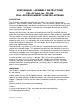
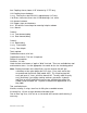
Appendix B PATTERNS AND GRAPHS The following patterns are based on NEC-2 modeling. They do not represent measured patterns. However, both forward gain and relative response Front to Rear (F/R ratio) have been verified (for relatively clean sites) by antenna range field strength measurements. Patterns actually achieved in practice will be affected by many aspects of the actual site where the antenna is installed.
Figure 2-B 2D-40A Elevation Plot (antenna mounted 70 feet above earth) Figure 3-B 2D-40A Azimuth Plot (antenna mounted 70 feet above earth) Revised 14 June 2003 B-2
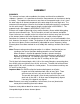
The following VSWR vs frequency plot was generated by the NEC-2 model. Actual measurements of real antennas in the field have typically reproduced the general shape of this curve. But the measured curves have shown a somewhat wider bandwidth between the 2:1 VSWR points. This is due to measurements being taken at the transmitter end of fairly long pieces of coax and to coupling of the antenna to the “stuff” in its near field region.
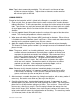
Appendix C MECHANICAL DRAWINGS 409 in (maximum boom center to element tip) (changes with tuning) 44.5 in 52 in 66 in 42 59 15 15 19 27 50.5 (changes with tuning) 18 Individual tubing dimensions are "exposed" lengths not including portion telescoped into next larger sized tubing. 2D-40A Front Element Overall Dimensions (element half length) 436.5 in (maximum boom center to element tip) (changes with tuning) 72 in 52 in 66 in 42 59 15 19 27 50.
Appendix D PARTS LIST 1 assy. BOOM, consisting of: 1 assy. MOUNTING PLATE, BOOM-TO-MAST, CONSISTING OF: 1 ea. Mounting Plate, Mast, DWG. No. 020218-001-0001 4 assy. Clamp, 2", Stainless, ASSY/N MC9200SSA 1 ea. Mounting Plate, Boom, DWG. No. 020215-001-0001 4 assy. Clamp, 3", Stainless, ASSY/No. MC9300SS 4 ea. Bolt, Hex head, 3/8-16 x 1", Stainless 1 ea. Bolt, Hex head, 3/8-16 x 1.25", Stainless 5 ea. Nut, 3/8-16, Stainless 21 ea. Lock washer, split ring, 3/8", Stainless 1 ea. BOOM CENTER TUBE, 3.00" dia.
1 ea. Upper bushing piece, acrylic, DWG. No. 020221-001-0001 4 ea. Screw, 10-24 x 1", Phillips pan head 8 ea. Washer, flat, stainless, AN-960C10 4 ea. Nut, elastic stop, 10-24, stainless 1 ea. Block, Insulating, acrylic, DWG. No. 020221-003-0001 2 ea. Screw, 10-24 x 1" Stainless 2 ea. Washer, flat, AN-960C10 4 ea. Washer, flat, #10 x 0.625", .188 hole, $$, P/N 10N62FENS 2 ea. Lock washer, split-ring, #10, Stainless 2 ea. Nut, 10-24, Stainless 1 assy. Front hairpin line, welded, with 2 tubes, 0.375 dia.
1 ea. Washer, Flat, AN-960C416 1 ea. Nut, Elastic Stop, 1/4"-20, Stainless 2 ea. Clamp, hose, all stainless, 71/95 mm, UPG P/N 4150 2 kit, STRAP, CONNECTING, HAIRPIN TO ELEMENT, consisting of: 2 ea. Strap, connecting, 0.625" wide, 8.5" long, DWG. No. 020219-003-0001 8 ea. Washer, flat, #10 x 0.750", .250” hole, $$, P/N 10N75FENS 4 ea. Washer, flat, #10 x 0.625”, .188” hole, $$, P/N 10N62FENS 4 ea. Washer, lock, split ring, #10, stainless 4 ea. Nut, 10-24, stainless ELEMENTS 1 assy.
6 ea. Washer, flat, AN-960C-416, stainless 2 ea. Washer, lock, split-ring, 1/4", stainless 2 ea. Nut, 1/4-20, stainless 2 ea. Tube Assy., 2.50" dia. 71.875" overall, all exposed, with 41" internal doubler, DWG. No. 020506-002-0001 2 ea. Tube, 2.25" dia., 0.125 wall, 58.75" overall, 52.0" exposed 2 ea. Tube, 1.875" dia., 0.125 wall, 72.0" overall, 66.0" exposed 2 ea. Tube, 1.50" dia., 0.095 wall, 47" overall, 42" exposed 2 ea. Tube, 1.25" dia., 0.083 wall, 63.5" overall, 59" exposed 2 ea. Tube, 1.00" dia.
Appendix E OPERATIONAL NOTES Feed System Description for the N7CL Array The N7CL version of the two element driven array has been described incorrectly as being essentially an HB9CV antenna. While the N7CL driven array antenna is definitely in the same class of antenna as the HB9CV (also confused with the ZL-Special), the N7CL Array is not technically very similar to either of the above versions of the two element driven array.
6. The design of the feed system rigidly enforces precise electrostatic balance for the array. Balance is maintained with regard both to the feedline connection and to the connection to the tower. This makes the antenna much quieter on receive and eliminates the need for a separate BALUN or coil of coax in the feedline to the transmitter. This balancing and matching scheme can handle virtually unlimited amounts of power (in amateur radio terms) without any non-linear effects or failure due to heating.
Tune-up Instructions for the Cal-Av Labs, Inc. Model 2D-40A Antenna This manual contains tabular data on the tuning and matching stub shorting strap positions and element lengths for an antenna mounted at the minimum recommended height of 1/2 wavelength above local earth and additional data for antennas mounted at one wavelength. However, the local environment (ground constants, vegetation, site clutter, etc.) makes it impossible to predict exactly what you will find when you raise the antenna at your site.
Antenna Settings for 2D-40A Mounted at 70 feet (one half wavelength) Frequency (MHz) Delta (inches) Tip Length (inches) 6.962 0 50.5 7.030 -5 45.5 7.099 -10 40.5 7.170 -15 35.5 7.241 -20 30.5 7.313 -25 25.
However, if you wish to achieve perfection at some particular frequency, here is the procedure to completely optimize the antenna for operation on a particular frequency: 1. If the minimum SWR is low enough to make you happy, proceed to step 6 below. If not, then adjust the matching (front) stub for minimum SWR as indicated in the subsequent steps. 2. First, find the frequency of minimum SWR (don't worry about the frequency where this occurs yet). 3.
Antenna Settings for 2D-40A Mounted at 140 feet (one full wavelength) Frequency (MHz) Delta (inches) Tip Length (inches) 6.948 0 50.5 7.015 -5 45.5 7.084 -10 40.5 7.154 -15 35.5 7.224 -20 30.5 7.296 -25 25.
Appendix F PAINTING INSTRUCTIONS GENERAL: Should you paint your antenna? We think so, but it's your decision. Here are the facts: OPERATIONAL EFFECTS: Nil; a thin dielectric coating (paint) between the metal and the air does cause changes, but they would be very difficult to measure for antennas of this size. A slight reduction in precipitation static may be noticed.
has some very nice attributes. Among them are that it can easily be removed with acetone, even after it is dry, and that it is very easy to touch up, while wet, after it's dry, or days later. It will oxidize a bit after years in the sun; even then, it can be cleaned with an MEK-dampened rag, just enough to remove dirt and some of the oxidized paint, and then repainted. We recommend two coats, at least 15 minutes time between coats.