
User Guide
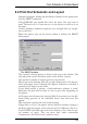


It is possible to select which sheets from a schematic diagram are prin
-
tedusingthe Sheets box.ThisonlyappearsintheSchematicEditor.
The Page... button brings you to another window that permits various
pagesettings.
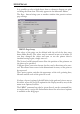
PRINT:PageSetup
The edges of the print can be defined with the aid of the four entry
boxes under Border. The values may be entered in mm or in inches. If
you have changed the values and want to use the printer driver's
standardsettingsagain,simplyentera 0.
The Vertical and Horizontal boxes allow the position of the printout on
thesheettobespecified.
Calibrate allows correction factors for the x and y directions to be ente
-
red. This allows linear errors in the dimensional accuracy of the print to
becorrected.
The Caption option switches the appearance of the title, printing date,
filenameandthescaleoftheprintonoroff.
If, when a layout is printed, the drill holes in the pads and vias are not to
be visible, select the No Drills option for the Display mode by way of the
menuitem Options/Set/Misc.
The PRINT command can also be given directly on the command line,
or can be run by a script file. Information about the selection of options
isavailableonthehelppages.
134
EAGLEManual