
User Guide


which the polygon is drawn (see page 116). You can also specify whether
or not vias are to be connected through thermals. The minimum clear
-
ances from elements carrying other signals specified in the Design Rules
are maintained (Clearance and Distance tabs). Changes are shown in the
layoutwhenthepolygonisnextcomputed(RATSNESTcommand).
In this way you can also create layers in which several areas are filled
with different signals. In that case you can assign different ranks (priori
-
ties) for the polygons. The rank property determines which polygon is
subtracted from others if they overlap. Rank = 1 signifies the highest
priority in the layout; nothing will be subtracted from such a polygon
(with the exception of polygons with rank = 0, drawn as a part of a
package in the Package Editor). Rank = 6 signifies the lowest priority.
PolygonswiththesamerankarecomparedbytheDRC.
Please read the notes regarding polygons in the section on Defining a
CopperPlane onpage 115.
Do not choose the wire width for polygons too fine! This can lead to
hugeamountsofplotdata andproblemsforthemanufacturingprocess.
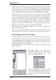
Power SupplyLayerwithOneSignal
A power supply layer with one signal is implemented by renaming one
of the Route2...15 layers in such a way that the new name consists of the
corresponding signal name prefixed by a $ sign. If, for example, the sig
-
nal called GND is to be realized as a power supply layer, then a layer is
specifiedashavingthename$GND.
The DISPLAY menu shows only those layers defined in the Layer setup of
theDesignRules!
For this purpose you activate the
DISPLAY command. You select layer 2
from the menu with the mouse. Then
clickonthe Change button.
Enter the signal name for the layer, and
activate the Supply layer check box. If the
layer is to be visible in the layout imme
-
diately, then click also on the Displayed
checkbox.
122
EAGLEManual